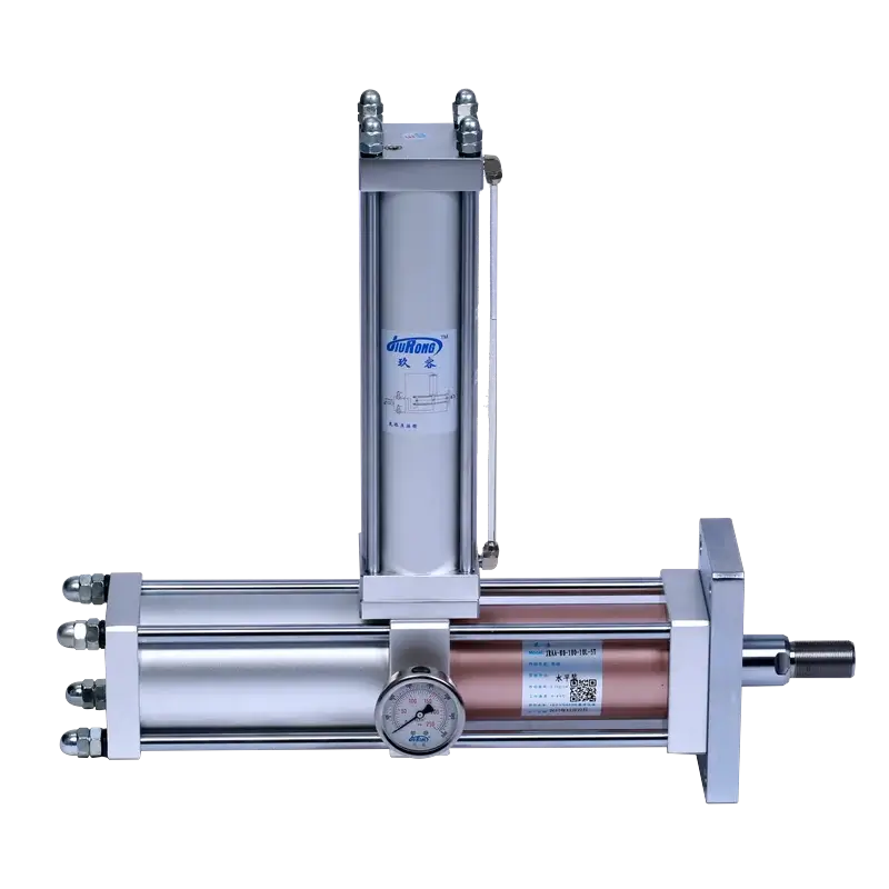
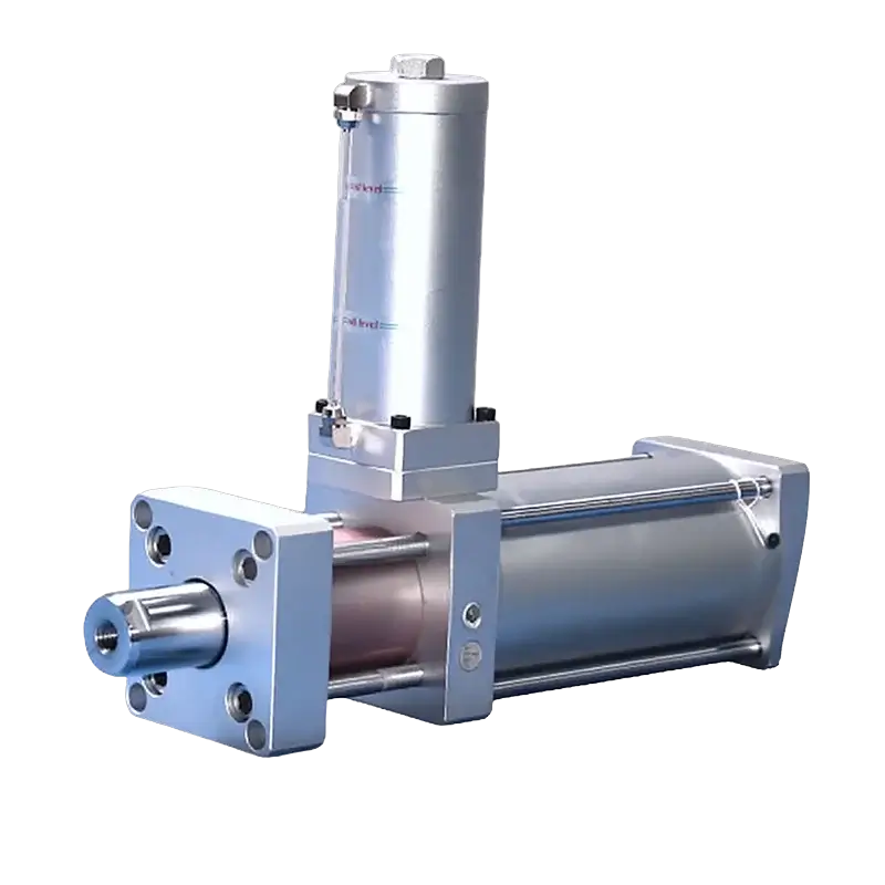
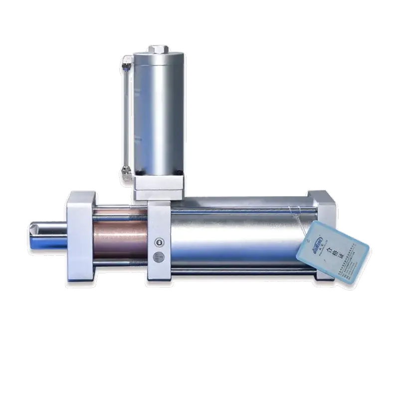
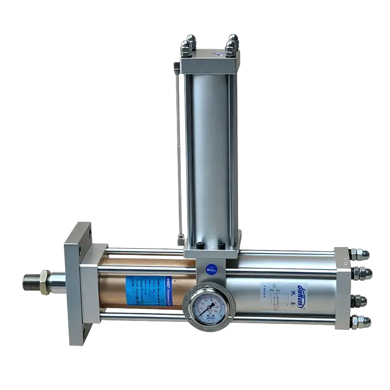
JRAA Horizontal Standard Hydro-pneumatic Cylinder
Horizontal-mount variant of the JRA pre-press cylinder. Designed for side-load applications where vertical mounting is impractical — extrusion, bending, horizontal pressing, and inline assembly lines from 1 to 40 tons.
Technical Specifications
Performance
| Output Force Range | 1–40 Tons (custom to 150T) |
| Boost Ratio | Up to 50:1 (model dependent) |
| Total Stroke | 10–300 mm |
| Boost (Power) Stroke | 5–50 mm |
| Repeatability | ±0.02 mm |
| Pre-press Speed | 50–500 mm/s |
| Boost Speed | 5–50 mm/s |
| Cycle Frequency | 25–45 cycles/min |
Pneumatic & Fluid
| Operating Pressure | 4–7 kgf/cm² (0.4–0.7 MPa) |
| Actuation Type | Double-acting |
| Hydraulic Fluid | VG68# anti-wear hydraulic oil |
| Air Cylinder Pressure Rating | 30 kgf/cm² |
| Oil Cylinder Pressure Rating | 120 kgf/cm² |
| Air Port Size | G3/8" – G1/2" (bore dependent) |
| Working Temperature | 0–60 °C |
| Lubrication | Oil-internal (sealed system) |
Mechanical
| Bore Sizes | ∅63, 80, 100, 125, 160 mm |
| Body Material | Aluminum alloy / steel |
| Mounting Orientation | Horizontal (Type A foot / Type B flange) |
| Rod End Thread | M22×1.5 – M30×1.5 (bore dependent) |
| Air Stroke Tolerance | +1.00 / 0.00 mm |
| Boost Stroke Tolerance | +0.20 / 0.00 mm |
| Seal Type | Multi-stage composite seals |
| Custom Options | Up to 150T, special strokes, mounting |
Force vs. Displacement Profile
The JRAA delivers two distinct force regimes in one cycle. Fast approach uses low air force for speed; the boost phase triggers high-force oil intensification over the final millimeters.
Pneumatic Circuit Diagram
The JRAA uses two solenoid valves (DT1/DT2) to independently control the pre-press air cylinder and the boost intensifier. This 4-port design enables the two-stage force profile, identical to the JRA circuit but oriented for horizontal mounting.
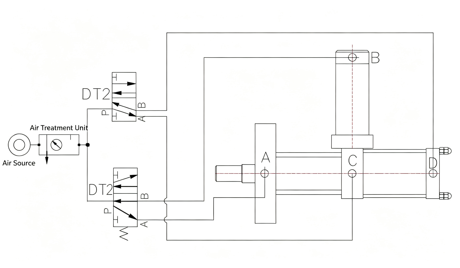
Flow: Air Source → Air Treatment Unit (FRL) → DT1 (5/2 valve) → P1/P2 pre-press extend & return → DT2 (3/2 valve) → P3/P4 boost activate & return → Two-stage high-force output
Mounting Configurations
The JRAA supports two horizontal mounting styles. Select Type A for foot-mounted installations or Type B for flange-mounted installations when ordering.
Type A — Foot Mount
Cylinder rests on two foot brackets bolted to a horizontal surface. Ideal for machine frames, extrusion lines, and fixtures where the cylinder sits on a base plate. Most common JRAA configuration.
Type B — Flange Mount
Front flange plate bolts directly to a vertical machine wall or bulkhead. Rod extends through the mounting surface. Compact installation for die sets, press tooling, and tight-space integration.
Installation Dimensions
Standard JRAA horizontal mounting dimensions by bore size. Model numbers shown with -A (foot mount) suffix. Add -B for flange mount. Full CAD drawings (DWG/STEP) available on request.
| Model | Force | Overall Length (retracted) | Flange Width (across flats) | Center Locating Diameter | Flange Outer Diameter | Piston Rod Diameter | Mounting Hole (n×∅) | Rod End Thread | Air Port Thread |
|---|---|---|---|---|---|---|---|---|---|
| JRAA-63-50-5L-1T-A | 1T | 310 | 240 | 50 | 80 | 25 | 4-∅9 | M22×1.5 | G3/8" |
| JRAA-63-100-10L-1T-A | 1T | 360 | 240 | 50 | 80 | 25 | 4-∅9 | M22×1.5 | G3/8" |
| JRAA-63-150-10L-1T-A | 1T | 410 | 240 | 50 | 80 | 25 | 4-∅9 | M22×1.5 | G3/8" |
| Model | Force | Overall Length (retracted) | Flange Width (across flats) | Center Locating Diameter | Flange Outer Diameter | Piston Rod Diameter | Mounting Hole (n×∅) | Rod End Thread | Air Port Thread |
|---|---|---|---|---|---|---|---|---|---|
| JRAA-80-100-10L-3T-A | 3T | 350 | 240 | 60 | 100 | 30 | 4-∅11 | M26×1.5 | G3/8" |
| JRAA-80-100-10L-5T-A | 5T | 350 | 240 | 60 | 100 | 30 | 4-∅11 | M26×1.5 | G3/8" |
| JRAA-80-150-15L-5T-A | 5T | 400 | 240 | 60 | 100 | 30 | 4-∅11 | M26×1.5 | G3/8" |
| JRAA-80-200-20L-5T-A | 5T | 450 | 240 | 60 | 100 | 30 | 4-∅11 | M26×1.5 | G3/8" |
| Model | Force | Overall Length (retracted) | Flange Width (across flats) | Center Locating Diameter | Flange Outer Diameter | Piston Rod Diameter | Mounting Hole (n×∅) | Rod End Thread | Air Port Thread |
|---|---|---|---|---|---|---|---|---|---|
| JRAA-100-100-10L-10T-A | 10T | 400 | 280 | 75 | 120 | 35 | 4-∅13 | M30×1.5 | G1/2" |
| JRAA-100-150-15L-10T-A | 10T | 450 | 280 | 75 | 120 | 35 | 4-∅13 | M30×1.5 | G1/2" |
| JRAA-100-200-20L-10T-A | 10T | 500 | 280 | 75 | 120 | 35 | 4-∅13 | M30×1.5 | G1/2" |
| JRAA-100-250-20L-10T-A | 10T | 550 | 280 | 75 | 120 | 35 | 4-∅13 | M30×1.5 | G1/2" |
| Model | Force | Overall Length (retracted) | Flange Width (across flats) | Center Locating Diameter | Flange Outer Diameter | Piston Rod Diameter | Mounting Hole (n×∅) | Rod End Thread | Air Port Thread |
|---|---|---|---|---|---|---|---|---|---|
| JRAA-125-100-10L-15T-A | 15T | 440 | 320 | 90 | 150 | 40 | 4-∅13 | M33×1.5 | G1/2" |
| JRAA-125-150-15L-20T-A | 20T | 490 | 320 | 90 | 150 | 40 | 4-∅13 | M33×1.5 | G1/2" |
| JRAA-125-200-20L-20T-A | 20T | 540 | 320 | 90 | 150 | 40 | 4-∅13 | M33×1.5 | G1/2" |
| JRAA-125-300-30L-20T-A | 20T | 640 | 320 | 90 | 150 | 40 | 4-∅13 | M33×1.5 | G1/2" |
| Model | Force | Overall Length (retracted) | Flange Width (across flats) | Center Locating Diameter | Flange Outer Diameter | Piston Rod Diameter | Mounting Hole (n×∅) | Rod End Thread | Air Port Thread |
|---|---|---|---|---|---|---|---|---|---|
| JRAA-160-100-10L-30T-A | 30T | 500 | 380 | 110 | 180 | 50 | 4-∅17 | M42×2 | G3/4" |
| JRAA-160-150-15L-30T-A | 30T | 550 | 380 | 110 | 180 | 50 | 4-∅17 | M42×2 | G3/4" |
| JRAA-160-200-20L-40T-A | 40T | 600 | 380 | 110 | 180 | 50 | 4-∅17 | M42×2 | G3/4" |
| JRAA-160-300-30L-40T-A | 40T | 700 | 380 | 110 | 180 | 50 | 4-∅17 | M42×2 | G3/4" |
All dimensions in mm. Dimensions shown for Type A (foot mount). Type B (flange mount) adds front flange plate. For custom configurations above 40T (up to 150T), contact engineering for detailed dimension sheets.
JRA vs JRAA: Which Mounting Orientation?
Both share the same pre-press boosting mechanism — identical force range, bore sizes, and two-stage cycle. The only difference is mounting direction. Choose based on how force must be applied in your machine.
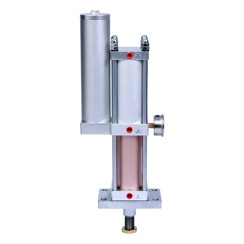
JRA
Vertical StandardRod pushes downward. Mounts on top of a fixture or press plate. The classic configuration for top-down work.
| Mounting | Vertical (rod-down) |
| Force Range | 1–40 T (custom to 150T) |
| Bore Sizes | ∅63 / 80 / 100 / 125 / 160 |
| Stroke | 10–300 mm |
- Vertical staking & riveting
- Top-down press-fit assembly
- Marking & embossing from above
- Presses with vertical tooling
JRAA
Horizontal StandardRod pushes horizontally. Mounts on a base plate (foot) or vertical wall (flange). For side-load applications where vertical mounting is impractical.
| Mounting | Horizontal — Type A foot / Type B flange |
| Force Range | 1–40 T (custom to 150T) |
| Bore Sizes | ∅63 / 80 / 100 / 125 / 160 |
| Stroke | 10–300 mm |
- Horizontal extrusion & bending
- Inline assembly line stations
- Side-press & horizontal forming
- Fixtures where rod must push sideways
Internal mechanism, force output, and pneumatic circuit are identical — only the mounting orientation and body configuration differ. Need a custom orientation? Contact our engineering team.
Build Your Model Number
Configure your JRAA and see the model code update in real time. Select your mounting type (A=foot, B=flange). The force output calculates automatically from your bore and air supply pressure.
Values are theoretical. Actual output may vary with seal friction, line losses, and hydraulic oil condition. For critical applications, apply a 1.5× safety factor.
Typical Applications
The JRAA is designed for horizontal-force applications — extrusion, bending, horizontal pressing, and inline assembly — across automotive, electronics, hardware, and appliance manufacturing.
Ready to Configure Your JRAA?
Send us your required tonnage, stroke, and mounting type (A=foot, B=flange). Our engineering team will reply with a quotation and dimension sheet within 24 hours.