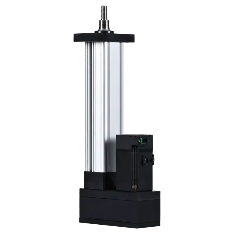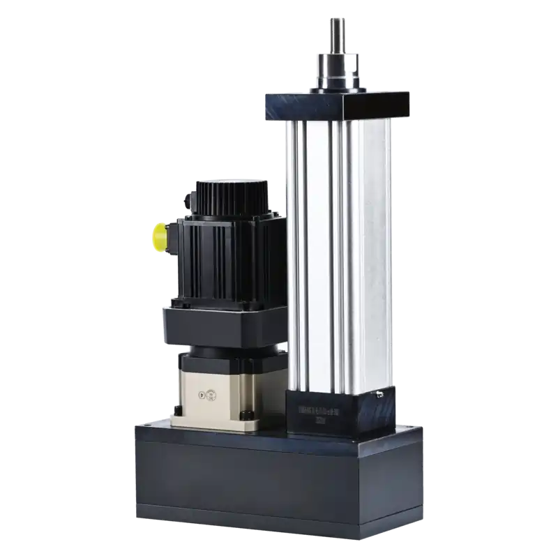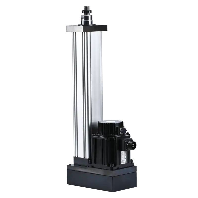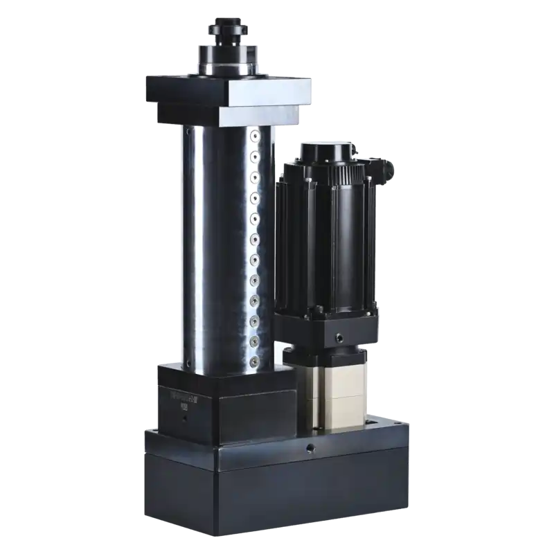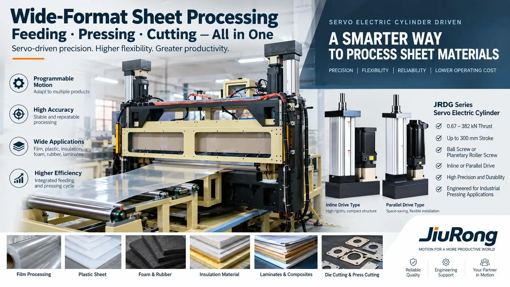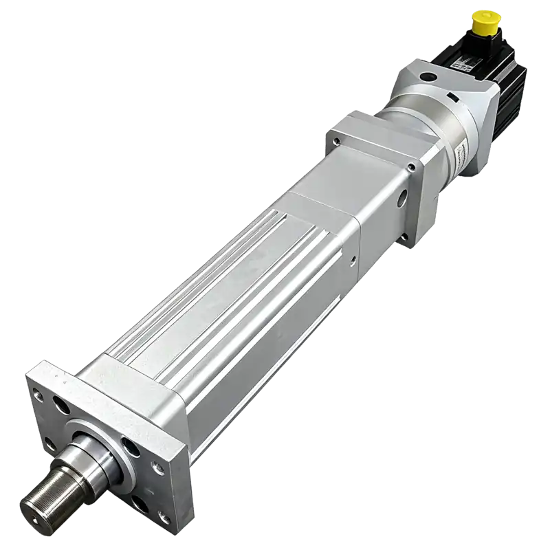
JiuRong® Electric Cylinder Series

Industrial linear actuator – Clean, Precise, Servo control

JiuRong Servo Electric Cylinders Series

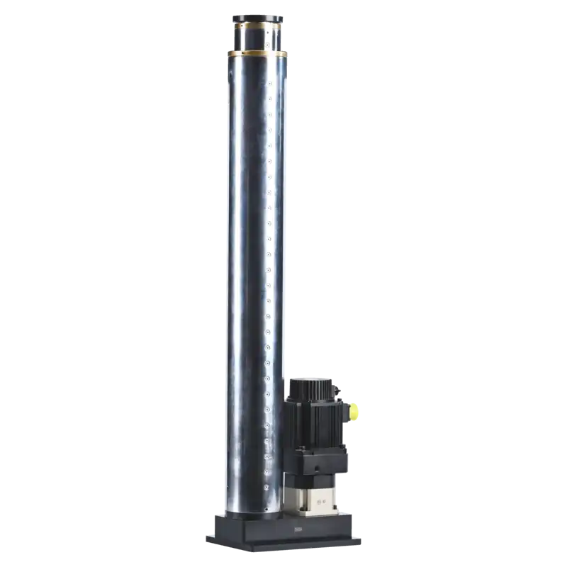
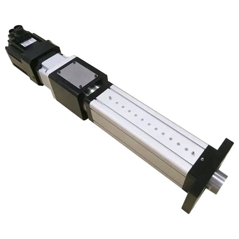
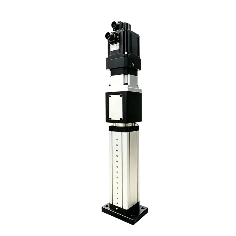
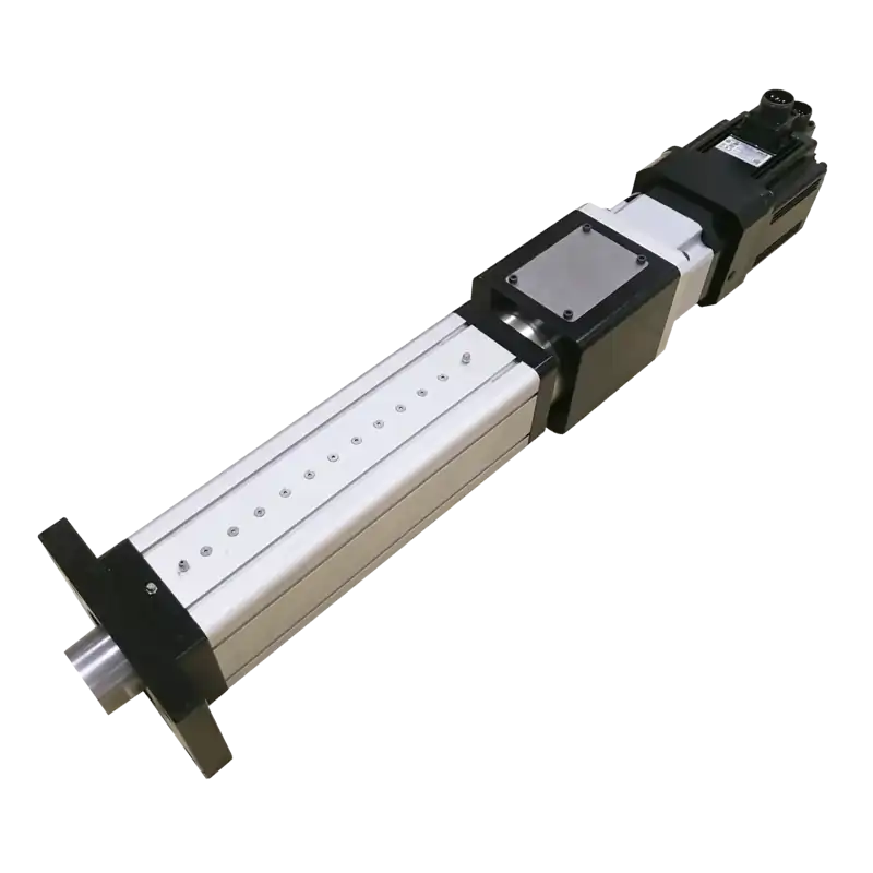
Definition: An electric cylinder—also called a servo electric cylinder or electromechanical linear cylinder—is a modular mechatronic actuator that converts rotary motion from a servo motor into precise linear reciprocating movement through mechanical transmission pairs such as ball screws, planetary roller screws, or gear trains. When paired with a servo drive, it delivers closed-loop control of position, velocity, and thrust directly from electrical power—eliminating the need for compressed air or hydraulic power units.

±0.005 mm

Micron-Level Repeatability

Closed-loop servo feedback ensures consistent positioning cycle after cycle.

0.1 – 500 kN

Wide Force Range

From delicate pressing to heavy‑duty industrial applications.

Up to 2 m/s

High-Speed Operation

Rapid cycle times for demanding automated production lines.

100M+ Cycles

Exceptional Durability

Planetary roller screw options for 24/7 continuous operation.

JiuRong® Electric Cylinder

Industrial-grade, servo-driven linear motion systems for automated manufacturing — exact control of force, position, and speed. Drop-in electromechanical replacements for pneumatic and hydraulic cylinders: cleaner operation, no oil mist, no leaks, higher controllability, and micron-level repeatability. Purpose-built for heavy payloads, long service life, and 24/7 production environments.

Request Engineering Support
ISO
9001:2015 Certified
18
Month Warranty
3D
Free Models
↔
Global Shipping
Start with your machine objective

Why Are You Considering an Electric Cylinder?

The correct product and supply scope depend on the change you need in the machine. Choose the closest objective before comparing specifications.

Replace Pneumatic Motion

Use electric motion when programmable positions, controlled acceleration, stable travel speed or recipe changeover creates measurable production value.

Potential value
Multi-position motion, reduced hard-stop adjustment and motion data
Engineering check
Cycle rate, required force at speed and whole-system energy
Decision boundary
A simple two-position pneumatic movement may remain the lower-cost solution.

⚙️ Electric Cylinder Component Structure

100% Customizable, Component Optional · Explore precision internal structure

Servo Electric Cylinder
Servo electric cylinder exploded section view
1
2
3
4
5
6
7
8
9
10
11
Component 01
Motion Housing
Coupling · Timing Belt Pulley Set
Fully enclosed motion housing that protects the Coupling or Timing Belt Pulley Set and front transmission. Provides dust sealing, noise reduction, and structural reinforcement; surface is corrosion resistant anodized.
Material6063 Aluminum Alloy
ProtectionIP65 Dustproof and waterproof
ProcessDie cast integrated
Noise ReductionBuilt in acoustic foam
11 Key Components
⚡ Energy Flow: Rotary → Linear
🔩 ISO 15552 Interface
🖱 Hover for details · Highlight sync
Motion and control path

How Command, Power and Feedback Create Linear Motion

A servo electric cylinder is the mechanical conversion stage inside a closed-loop axis. The command path tells the axis what to do, the power path creates motion, and feedback reports what the motor is doing. Process-force measurement is a separate loop when the workpiece result must be verified.

Command path
PLC / Motion ControllerTarget position, velocity or torque→Servo DriveCalculates motor current command→Servo MotorProduces controlled rotary torque
Mechanical power path
Motor ShaftRotary speed and torque→Coupling or Timing BeltInline connection or parallel ratio→Ball / Roller ScrewRotation converted into axial travel→Piston Rod + ToolLinear motion applied to the process
Motor feedback loop
EncoderMeasures motor shaft position and speed←Servo DriveCorrects position, velocity and motor torque

Encoder feedback closes the motor loop. It does not automatically measure tooling deflection, workpiece force or final load position.

Optional process measurement
Load Cell / External Linear ScaleMeasures force and/or load-side position→Process ControllerEvaluates limits and stores the result

Required when force-position curves, defect detection or traceable production acceptance are part of the machine function.

Ideal axial forceF ≈ 2πηT / lead

Ideal linear speedv = lead × rpm / 60

What the screw lead changes

A shorter lead generally favors force and lowers linear speed for a given motor. A longer lead generally favors speed and lowers available force. Belt or gearbox ratio further changes the motor-side requirement.

What still limits the real result

Motor torque-speed curve, drive current, supply voltage, acceleration, friction, thermal duty, screw life, buckling, guidance and machine stiffness must be evaluated together.

System boundary: position command, motor encoder feedback and process-force measurement are related, but they are not interchangeable specifications.

Choose the mechanical arrangement

Choose Your Product Family

Two servo electric cylinder families — each with internal configuration options. Select a family, then fine-tune drive type or stage count on the product page.

Single-Stage
Single-Stage Servo Electric Cylinder
JRDG Series · 10 sizes · JRDG44–265

Single-Stage Servo Electric Cylinder

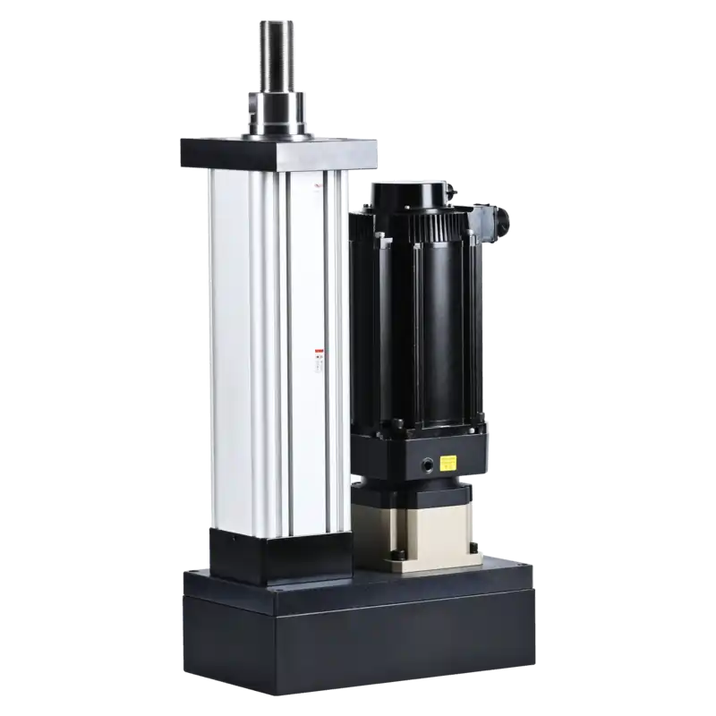
Standard single-stage platform with ball or roller screw. Thrust 0.67–382 kN, stroke 0–300 mm — choose the drive arrangement that fits your envelope and precision requirement.

Inline Direct Drive ≥90% efficiency · minimal backlash · highest rigidity · for precision positioning
Parallel Side-Mount 20–30% shorter axial · ratio via pulleys · belt damping · for space-constrained machines
  • Ball or planetary roller screw option
  • 8 mounting interfaces (FA / FB / TC / LA / RS / FG / CA / CB)
  • IP65 standard, IP66/67 optional
Best for: Precision pressing, positioning axes, test equipment, general automation View JRDG Series →
Multi-Stage Telescopic
Multi-Stage Telescopic Servo Electric Cylinder
JRDJ Series · 6 sizes · JRDJ87–163

Multi-Stage Telescopic Servo Electric Cylinder

Nested multi-stage screw extends 3–10× retracted length. Aluminum or steel barrel, up to 3750 mm stroke from a compact stored package — choose stage count by stroke and load.

3-Stage 3:1 extension ratio · JRDJ-87/88/115/163 · thrust 0.76–19 kN
4-Stage 10:1 extension ratio · JRDJ-145/147 · up to 3750 mm stroke · longer reach
  • Aluminum (light) or 20# steel (heavy) barrel
  • Spring holding brake standard on vertical installs
  • ±0.02 mm positioning, ±0.01 mm with glass scale
Best for: Stage lifts, space-limited automation, long-stroke deployment, hatch actuation View JRDJ Series →
Servo Electric Cylinder Families

Four duty classes — from precision automation to heavy pressing

Choose by force, stroke and application. Each card shows the drive type, key specs and typical uses.

Compact inline electric cylinder — planetary reducer
Compact inline electric cylinder — flange mount
Compact inline electric cylinder — 1 ton
Compact inline electric cylinder — alternative view
Electronic assembly · precision testing · clean-room · small-part positioning
01
Inline drive · ≤ 5 kN

Precision Automation

Direct-drive inline cylinder for electronic assembly, testing and small-part handling where accuracy matters more than raw force.

  • Repeatability ±0.01 mm with optional glass scale
  • Efficiency ≥ 90% — no belt losses, no tension adjustment
  • Maintenance no belts, no pulleys, lube-for-life option
Force ≤5 kN · Series JRDG 44·53·60 · Accuracy ±0.01 mm · IP54
View JRDG Series →
Medium parallel electric cylinder — standard
Medium parallel electric cylinder — side view
Automotive pressing · automation lines · packaging · lifting platforms
02
Parallel drive · 5 – 60 kN

General Industrial

Belt-driven parallel cylinder with adjustable ratios — the workhorse for automation lines, automotive pressing and lifting platforms.

  • Shorter length axial length cut 20–30% vs inline equivalent
  • Adjustable ratio pulley swap from 1:1 to 5:1 without disassembly
  • Serviceability motor replaces in minutes without touching the cylinder
Force 5–60 kN · Series JRDG 75·95·110·138 · Length −30% · IP65
View JRDG Series →
Heavy duty electric cylinder — large
Heavy duty electric cylinder — high thrust
Heavy duty electric cylinder — steel housing
Heavy pressing · forging · extrusion · new-energy battery assembly
03
Reinforced · roller screw · 60 – 382 kN

Heavy Pressing & Forming

Reinforced steel housing with roller-screw option for sustained force — built for stamping, forging, extrusion and new-energy assembly.

  • Roller screw planetary multi-roller engagement for high load and cycles
  • Continuous duty sized for thermal limit, not just peak force
  • Rigid housing welded/steel frame absorbs reaction, not the machine
Force 60–382 kN · Series JRDG 170·220 · Roller screw option · IP65
View JRDG Series →
Telescopic multi-stage electric cylinder
Stage lifts · AGV masts · aerial work · hidden installation
04
Multi-stage · ≤ 3750 mm stroke

Space-Limited Long Stroke

Nested multi-stage screw extends 3–10× retracted length — for lift platforms, AGV masts, aerial work and hidden mounting.

  • Long stroke up to 3750 mm from a fraction of the retracted length
  • Closed-loop ±0.01 mm positioning with integrated encoder
  • Vertical safe spring holding brake standard on vertical installs
Stroke ≤3750 mm · Ratio 3–10× · Series JRDJ 87–163 · Force 0.76–4.8 kN
View JRDJ Series →

Ball screw or roller screw?

The duty profile decides — not the brochure

Ball Screw

General duty

Proven rolling-element drive for most positioning and pressing. Cost-effective, widely serviceable.

  • Efficiency 85 – 95%
  • Light to medium loads
  • Short lead times
  • Medium cycle rates
Positioning · assembly · general pressing
Roller Screw

Extreme duty

Planetary multi-roller engagement distributes load over more contact area — for sustained force and high cycles.

  • Higher load per size
  • High-cycle resistant
  • Longer life under load
  • Stiffer under force
Stamping · extrusion · high-cycle · continuous load
Rated capability is the range — your application sets the number. Achievable performance depends on duty cycle, mounting stiffness and ambient conditions. We size to the application, not to the spec sheet.
Define the quotation boundary

What Does “Electric Cylinder Supply” Include?

Define supplier responsibility before quotation. A compatible mechanical cylinder, a working motion axis and a validated production process are three different deliverables.

01
Mechanical actuator

Electric Cylinder

  • Cylinder body and rod
  • Screw, nut and bearings
  • Seals and lubrication
  • Mounting interfaces

Mechanical product; cannot operate alone.

02
Motion package

Controlled Linear Axis

  • Servo motor and drive
  • Encoder, cables and switches
  • Coupling or belt ratio
  • Brake and fieldbus interface

Controls position and motion when correctly integrated.

03
Process system

Servo Process / Press Function

  • Load cell and calibration
  • Force-position controller
  • Process software and records
  • Frame, tooling, guarding and safety

Machine-level scope; never implied by actuator-only specifications.

RFQ rule: state whether you need the mechanical actuator, a matched motor-and-drive package, or a complete force-position process system.

Engineering Application Boundaries

Before Servo Electric Cylinder Selection

A servo electric cylinder may meet the required force and stroke specification, but real machine performance depends on load direction, motion profile, installation conditions, duty cycle and operating environment.

01

Electric cylinders are built for axial force. Side load shortens their life.

Load path: motor → screw → nut → rod → load. Any off-axis force creates a bending moment outside this designed path.

What we verify
  • Guide wear — uneven contact pressure raises friction, cuts positioning accuracy and service life.
  • Bearing overload — radial load on internal bearings causes premature fatigue and abnormal noise.
  • Screw derating — ball screws are axial-optimized; bending force reduces expected life.
Proven in
C-Frame Electronic Servo Press
C-frame structure with dual guide posts absorbs off-axis pressing force — cylinder sees only axial load.
Assessment: side force (N) · load offset (mm) · moment arm (mm) · accuracy (mm) · cycles
Electric cylinders are built for axial force. Side load shortens their life. Solution: external guidance
02

Long strokes are limited by buckling, not material strength.

Euler buckling: a slender compressed column can suddenly bend. Stroke length has a squared effect on allowable load. Mounting condition changes allowable load significantly.

What we verify
  • Stroke² effect — a longer stroke sharply reduces allowable compression force.
  • Push ≠ pull — no buckling in tension, so push and pull ratings can differ on the same cylinder.
  • Critical load — screw stiffness, screw Ø, unsupported length, mounting condition.
Proven in
Long-stroke screw machining
Precision-ground screw shafts up to 2 m — each sized with Euler buckling check before assembly.
Assessment: stroke (mm) · screw Ø (mm) · end fixing · compression (N) · safety factor
Long strokes are limited by buckling, not material strength. Solution: Euler calc + safety margin
03

Impact peak force can far exceed your specified force.

Stamping, riveting, press-fitting, rapid clamping. You may specify 10,000 N — the instantaneous peak during impact is much higher.

What we verify
  • Raceway damage — impact overloads the screw raceway.
  • Nut fatigue + coupling shock — mechanical clearance grows cycle by cycle.
  • Nominal ≠ peak — sizing to the nominal value alone invites premature failure.
Proven in
Precision Servo Radial Riveting Machine
Radial riveting generates 2–3× impact spikes — cylinder and drive sized to peak, not nominal force.
Assessment: peak force duration · impact frequency · acceleration profile
Impact peak force can far exceed your specified force. Solution: buffering + tuned curve
04

Peak force is not continuous force. The limit is heat.

Motor heating follows I²R — higher torque demand means higher current, and heat rises with the square of it.

What we verify
  • Thermal limit — continuous near-peak running raises motor temperature.
  • Drive trips — unplanned downtime costs more than the right motor.
  • Shorter motor life — sustained overload degrades windings and bearings.
Proven in
Connecting Rod & Piston Pin Press
Continuous pressing cycle — thermal derating verified with 750 W servo fan and duty-cycle monitoring.
Assessment: force (N) · motion/rest (s) · cycles/hour · accel (m/s²) · duty cycle (%)
Peak force is not continuous force. The limit is heat. Solution: bigger motor / roller screw
05

Max speed and max force cannot be delivered at the same time.

Motor power is P = F × v. Holding high force while raising speed demands disproportionately higher power. Acceleration demand often determines motor sizing more than maximum travel speed.

What we verify
  • Common misconception — the max speed spec is assumed to coexist with max force.
  • Power shortfall — missed target acceleration, positioning time overruns.
  • Drive overload — sustained overload trips the servo drive.
Proven in
Multi-Station Benchtop Servo Press
Rapid index between stations — motor sized to the accel/decel profile, not just max force.
Assessment: load (N) · speed (mm/s) · accel (m/s²) · cycle time (s) · motor sizing
Max speed and max force cannot be delivered at the same time. Solution: size to your duty
06

System accuracy is built, not bought.

A ±0.01 mm cylinder on a plate that deforms 0.05 mm delivers 0.06 mm system accuracy — the mounting erased the precision.

What we verify
  • Contributors — load stiffness, mounting structure, thermal expansion, screw grade, feedback.
  • Quantified — mounting deformation subtracts directly from system accuracy.
  • Feedback — linear scale recovers precision the screw alone cannot.
Proven in
3-Station Automatic Feeding Riveting Press
Welded machine frame + linear guides — repeatability held at ±0.02 mm across all three stations.
Assessment: positioning (mm) · repeatability (mm) · load condition · mounting rigidity
System accuracy is built, not bought. Solution: screw grade / linear scale
07

Vertical axes need a brake. Gravity doesn't wait.

Power loss = torque loss — on a vertical axis the load drops. Equipment, product, and operator are at risk.

What we verify
  • Motor brake — standard for vertical holding, between motor and transmission.
  • Safety-critical — redundant braking, mechanical locking, safety-rated control system when required by machine risk assessment.
  • Declare early — vertical + load + hold time must be stated at selection.
Proven in
Vertical-axis cylinder integration
Spring-applied holding brakes fitted as standard on all vertically mounted configurations.
Assessment: vertical load (kg/N) · gravity direction · hold time · safety class
Vertical axes need a brake. Gravity doesn't wait. Solution: brake / redundant braking
08

The environment decides reliability before the cylinder runs.

Dust, water, temperature extremes, corrosive media — each attacks seals, lubrication, surfaces, sensors.

What we verify
  • Predictable failures — seal failure, lubrication degradation, corrosion, sensor failure.
  • IP rating — protection must match the real environment, not a default.
  • Cleaning process — washdown and chemicals change the sealing spec.
Proven in
Pre-delivery performance testing
Every cylinder runs through load, cycle and environmental checks before shipment — IP65 as standard.
Assessment: IP rating · ambient temperature · contamination level · cleaning process
The environment decides reliability before the cylinder runs. Solution: IP65–IP67 protection
Process-to-architecture map

Start Selection from the Machine Task

Application names do not select a model by themselves. Identify what must be controlled and the risk that dominates the calculation.

Machine taskWhat must be controlledDominant engineering riskStarting architecture
Press-fitting & assemblySeating depth and force-displacement signatureFrame stiffness, working-speed force and load cellInline / Parallel
Riveting, clinching & crimpingJoining profile and per-cycle qualityPeak duration, impact and tooling guidanceInline / Parallel
Positioning & changeoverPositions, velocity and acceleration recipesRepeatability, controller, fieldbus and envelopeInline / Parallel
Lifting & vertical motionGravity load, holding and intermediate positionsBrake, buckling, regeneration and safetyParallel / Multi-stage
Testing & inspectionLoad or displacement waveformReversal frequency, life and sampling synchronizationInline
Long-stroke deploymentExtended travel from a short stored lengthStage stability, external guidance and bucklingMulti-stage

The existing Engineering Boundaries section explains failure risks in detail; the Quick Selector below provides a preliminary family direction.

Quick Selector

Find your cylinder in 4 steps

Based on the force, stroke, mounting and duty you need — get a preliminary configuration and the engineering points we verify before quoting.

1 2 3 4

What push force do you need?

Rated force at the rod. If you have a peak or impact load, factor it in — we verify that separately.

What stroke length?

Total rod travel. Longer strokes may require a larger screw diameter to resist buckling under compression.

Mounting direction?

Vertical axes need a holding brake. Horizontal is the simplest mounting case.

How will it be used?

The duty profile decides motor sizing, screw type and cooling — not just max force.

Preliminary Configuration

—

—

Architecture —
Force class —
Screw type —
Brake —
Direct engineering answers

Servo Electric Cylinder FAQ

Category-level answers for product comparison, preliminary selection and quotation scope.

What is a servo electric cylinder?

A servo electric cylinder is a rod-style electromechanical actuator. A motor rotates a ball screw or roller screw to create controlled linear travel.

Is an electric cylinder the same as a servo press?

No. The cylinder is the mechanical axis. A complete servo press also requires the motor and drive, force sensing, process controller, machine frame, tooling, safety controls and validation.

What data are required for selection?

Provide process force, moving mass, stroke, approach and working speeds, acceleration, dwell, cycle rate, mounting direction, guidance, design life, environment, controls and installation envelope.

Can maximum force and maximum speed be achieved together?

Not by assumption. Screw lead, motor torque-speed characteristics, drive current, voltage and thermal duty create a force-speed envelope that must be checked at the required operating point.

When is external guidance required?

Use external guidance when the load creates side force, offset force or overturning moment. The piston rod should primarily transmit axial force.

Should I choose a ball screw or roller screw?

Compare actual load rating, lead, speed, stiffness, calculated life, package size, serviceability and cost. Neither technology is universally better.

Can an electric cylinder replace a pneumatic or hydraulic cylinder?

It can when programmable motion, process feedback or removal of air or oil infrastructure creates value, but the complete force-speed-duty requirement and lifecycle cost must be compared.

What is normally included in a quotation?

Scope varies. Confirm whether the quotation covers the mechanical cylinder only, a matched motor-and-drive package, or a complete process system with sensing, controls and machine integration.

Engineering recommendation

Send the Duty, Not Just a Model Number

Your process and motion cycle determine the architecture, screw, motor interface and validation work. Provide the known inputs; unknown values can remain marked for engineering review.

You receive a clearer quotation basisArchitecture directionMissing-data listRequired engineering checksDefined supply scope

Minimum useful application data

  1. ProcessTask, axial force and moving mass
  2. MotionStroke, approach/work/return speed, acceleration and dwell
  3. DutyCycles per minute, hours per day and design life
  4. InstallationOrientation, side load, guidance, envelope and drawing
  5. EnvironmentTemperature, dust, water, chemicals and cleaning
  6. ControlsMotor, drive, PLC, fieldbus, brake and force-data need
Request Engineering Support →
Browse mode

Interested in learning more about JiuRong

Discover how our innovative solutions and advanced technologies can empower your projects to achieve more.

Get In Touch Now