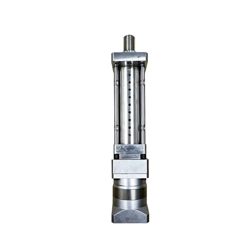
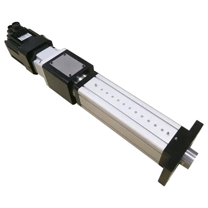
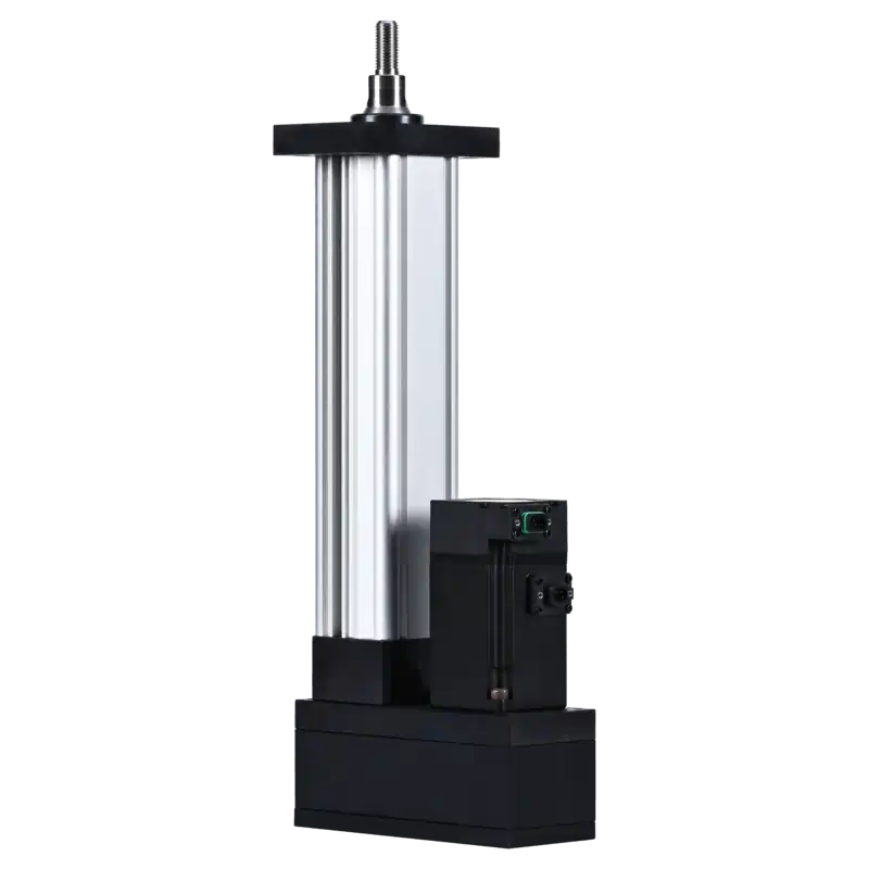
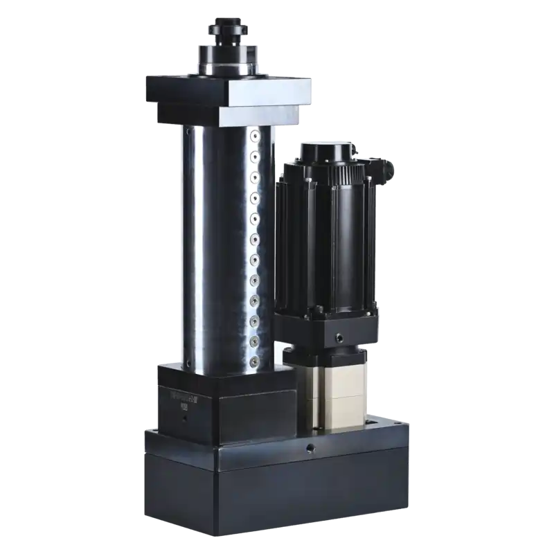
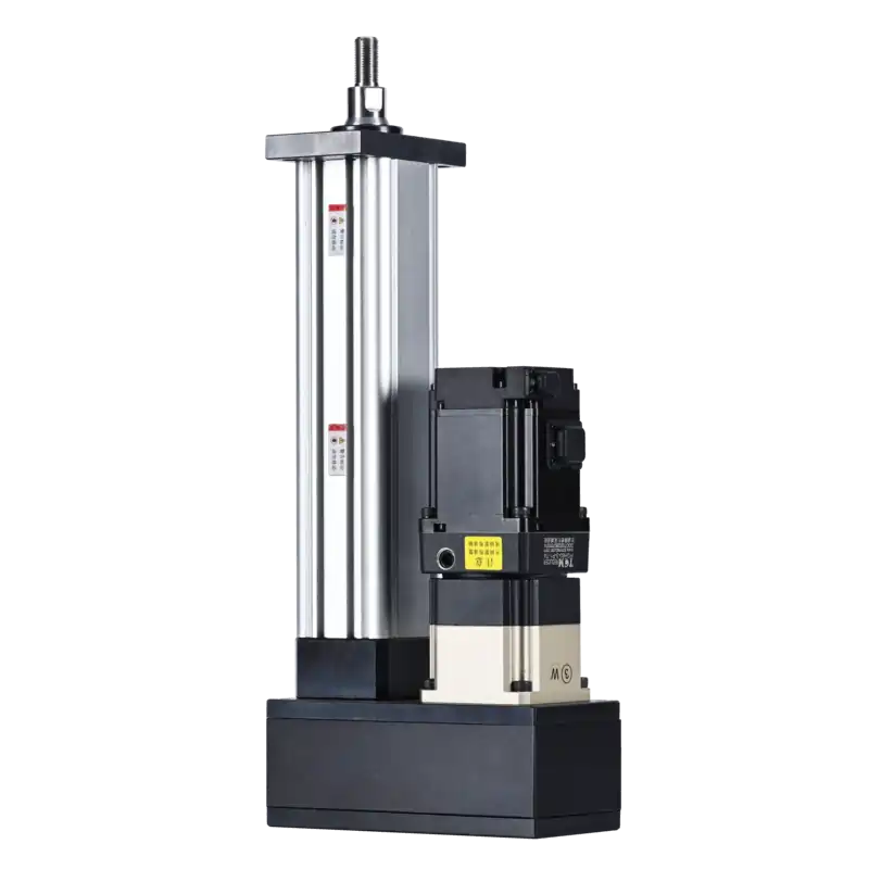
JRDG Single-Stage Servo Electric Cylinder
Programmable electromechanical linear actuation for precision press fitting, positioning, and cyclic testing. Replace pneumatic and hydraulic cylinders with clean, traceable, recipe-controlled motion — from compact 44 mm frames to heavy-duty 265 mm frames delivering up to 382 kN observed thrust.
Six Problems That Drive Pneumatic-to-Electric Conversion
If any of these sound familiar, a JRDG servo electric cylinder may be the right upgrade path. Each pain point below maps to a specific electromechanical capability — and a qualification check before you commit.
Pneumatic Motion Won't Hold Position
Mechanical stops, manual adjustment, scrap, slow changeover
JRDG answer: Programmable multi-position motion with stored recipes and controlled acceleration. Change position, speed, and force in software — no mechanical stops.
Hydraulic Leakage & Cleanroom Risk
Contamination, maintenance work, heat, floor-space burden
JRDG answer: Electromechanical actuation removes the local hydraulic circuit entirely. Clean operation, no oil leaks, no power-unit heat — ideal for controlled environments.
Assembly Quality Can't Be Traced
Latent defects, manual inspection, disputed quality, hard root-cause
JRDG answer: Integrate force and position measurement with process windows and record retention. Every press-fit cycle generates a traceable force-displacement signature.
Frequent Product Variant Changeover
Setup time, operator error, dedicated tooling
JRDG answer: Recipes change position, velocity, acceleration, and process steps in software. One cylinder handles multiple SKUs without mechanical reconfiguration.
Installed Length Doesn't Fit the Machine
Enclosure redesign or unusable stroke
JRDG answer: Parallel motor arrangement shortens axial envelope. Compare full installed envelope — not just cylinder body length — to find the right fit.
Existing Actuator Fails Early
Downtime, screw/bearing replacement, accuracy drift
JRDG answer: Engineering recalculates equivalent load, buckling, side load, lubrication, alignment, and duty. Replacing by headline thrust alone without finding the failure mode is insufficient.
Single-Stage Screw-Driven Electromechanical Actuation
The JRDG converts rotary servo motion into precise linear force through a single-stage screw drive. Direct and parallel arrangements are drive configurations within the same family — not separate product series.
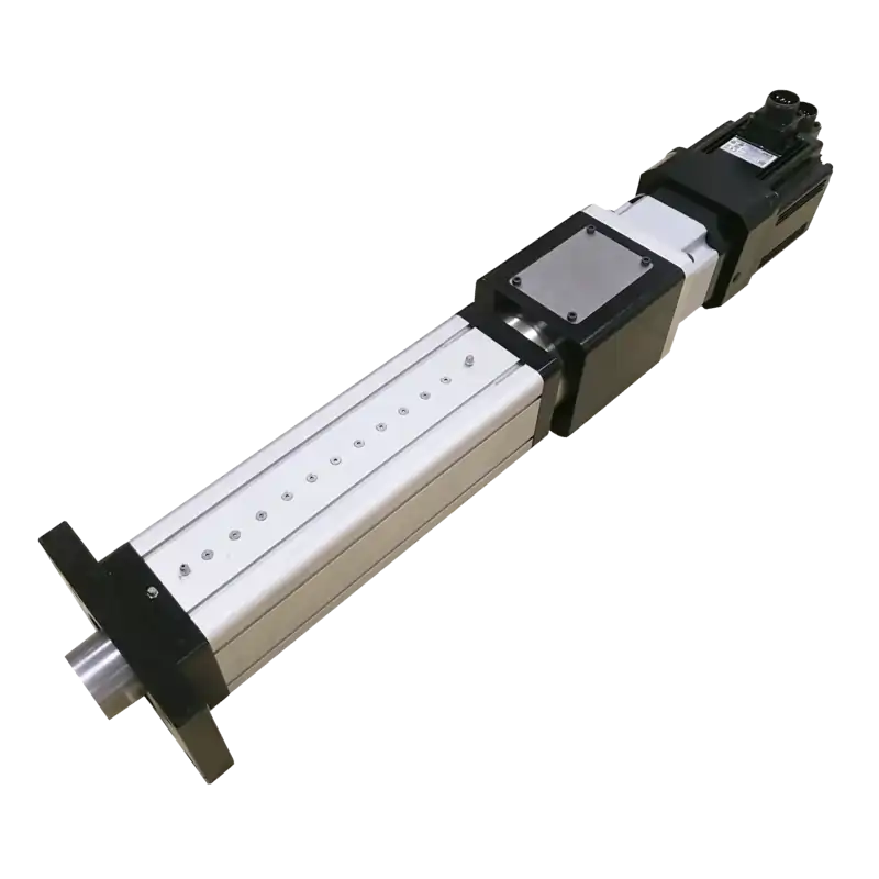
How the JRDG Works
A servo motor rotates a ball screw or roller screw through an inline coupling or parallel belt transmission. The screw converts rotary motion into axial travel; encoder and drive close the position, speed, and torque loops. Force relationship: F = (2π · η · T) / lead — shorter lead raises thrust but lowers speed for a given motor speed.
- Single-stage screw drive — direct mechanical path from motor to output rod, minimizing backlash and maximizing rigidity. No telescopic stage synchronization needed.
- Direct & Parallel drive — two motor coupling arrangements share the same cylinder body and screw assembly. Direct = in-line motor; Parallel = side-mounted with belt/gear transmission.
- Configuration-dependent performance — thrust, speed, and duty cycle vary by size model, drive arrangement, screw lead, and motor selection. No single family-wide maximum applies.
- Servo-controlled precision — compatible with servo drives and controllers for programmable position, velocity, and force profiles. Controller/drive attributes, not cylinder body attributes.
Is JRDG the Right Fit for Your Application?
Use this quick qualifier to determine whether JRDG is a strong candidate, or whether an engineering review is needed before selection.
Good Fit Likely Match
Applications where the JRDG's core capabilities align directly with requirements:
- Press fitting, insertion, and assembly operations requiring controlled force
- Precision positioning and feeding with programmable motion profiles
- Cyclic testing and fatigue simulation with repeatable load-displacement curves
- Pneumatic or hydraulic cylinder replacement for cleaner, controllable actuation
- Force requirements within loaded size-model ranges (0.67–382 kN observed)
- Multi-position recipe changeover without mechanical adjustment
Engineering Review Required Verify First
Conditions that require engineering validation before committing to a configuration:
- High side-load or moment loads on the output rod
- Extended vertical mounting without fail-safe braking
- Continuous 24/7 duty cycles or high-frequency thermal loading
- Precision requirements below ±0.05 mm (accuracy, repeatability, and resolution are separate parameters)
- IP65+ washdown or corrosive environment specifications
- Force/speed/stroke combinations at the extreme of any loaded range
- Applications requiring JRDG205 or JRDG295 (records pending)
- Uncontrolled impact or severe shock loading
Minimum Inputs for Engineering Qualification
Size Model Comparison
Browse loaded JRDG size models by frame, thrust, speed, stroke, and motor power. This is a candidate-filtering tool — final configuration requires engineering verification.
| Size Model | Max Stroke | Rated Thrust (kN) | Rated Speed (mm/s) | Motor Power (kW) | Config Records | Drive Mapping | Status |
|---|---|---|---|---|---|---|---|
| JRDG44 | 300 mm | 0.85 | 100 | 0.1 | 1 | Not explicit | Partial |
| JRDG53 | 400 mm | 0.68–1.0 | 167–250 | 0.2 | 2 | Not explicit | Ready |
| JRDG60 | 800 mm | 0.67–5.0 | 83–500 | 0.4–0.75 | 11 | Not explicit | Ready |
| JRDG75 | 1000 mm | 6.4–10.2 | 6.25–125 | 0.4–1.0 | 16 | Explicit D/P | Ready |
| JRDG95 | 1500 mm | 17.8–38.2 | 47.6–83 | 1.5–3.0 | 12 | Explicit D/P | Ready |
| JRDG110 | 1500 mm | 15–49.6 | 50–250 | 2.9–4.4 | 12 | Explicit D/P | Ready |
| JRDG138 | 1500 mm | 6–61 | 41.6–250 | 2.9–4.4 | 12 | Explicit D/P | Ready |
| JRDG170 | 2500 mm | 112–153 | 33–100 | 4.4–11 | 12 | Explicit D/P | Ready |
| JRDG220 | 2500 mm | 280–382 | 33–71.4 | 15–23.6 | 12 | Explicit D/P | Ready |
| JRDG265 | 2500 mm | — | — | 23.6 | 0 | Not explicit | Partial |
| JRDG205 | Registry record pending — excluded from family maxima | Pending | |||||
| JRDG295 | Registry record pending — excluded from family maxima | Pending | |||||
Thrust and speed ranges are configuration-dependent and come from different drive/screw/motor combinations. They do not represent a single simultaneous operating point. JRDG44 has summary data only; JRDG265 performance configurations are in preparation.
Direct vs. Parallel Drive
Both arrangements share the same cylinder body and screw assembly. The choice affects overall length, inertia, speed-torque characteristics, and mounting envelope — not the thrust capability of a given frame size.
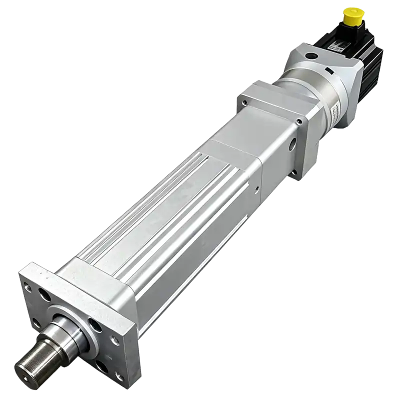
Direct Drive
Motor in-line with cylinder axis
The servo motor couples directly to the screw shaft through a rigid coupling. This one-to-one transmission minimizes mechanical backlash, offers the highest torsional rigidity, and delivers transmission efficiency above 90% — ideal for precision positioning and high-frequency cycling.
- Motor PositionIn-line with rod axis
- TransmissionDirect coupling (1:1)
- Efficiency≥ 90%
- BacklashMinimal
- Radial EnvelopeCompact
- Overall LengthLonger (motor in-line)
- Best ForPrecision, high rigidity
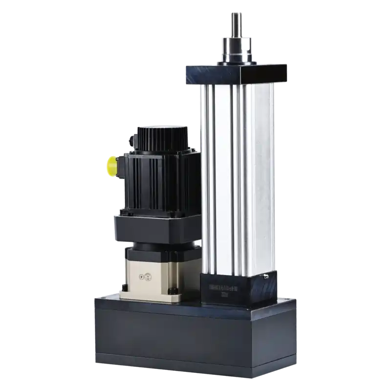
Parallel Drive
Motor side-mounted with belt drive
The servo motor mounts parallel to the cylinder axis, driving the screw through timing pulleys and a timing belt. This folding design reduces overall axial length by 20–30%, offers flexible reduction ratios via pulley swaps, and the belt absorbs shock and vibration — ideal for space-constrained machines.
- Motor PositionParallel to rod axis
- TransmissionTiming belt + pulleys
- Efficiency≥ 85%
- Axial Length20–30% shorter
- Radial EnvelopeWider
- Reduction RatioFlexible via pulleys
- Best ForSpace-constrained, shock loads
How to Choose: 3 Quick Questions
Build Your Model Number
Interactive configurator — select parameters to generate a complete JRDG part number. Stroke range 0–300mm. Thrust and speed are application-specific, confirmed by engineering.
From Family to Final Configuration
Follow this progressive sequence to narrow from product family to a specific configuration. Each step constrains the next — final compatibility is confirmed by engineering.
Size Model
Frame size by force & envelope
Drive Arrangement
Direct or Parallel
Stroke
Required travel length
Screw / Lead
Force-speed trade-off
Motor
Power & torque matching
Mounting
Front / rear / side flange
Options
Feedback, brakes, seals
Configuration Compatibility: This is a guided logic tool, not a final configurator. Where compatibility mapping is incomplete (particularly JRDG44/53/60 drive separation and JRDG265), do not assume a configuration is manufacturable. Submit your selection to engineering for compatibility verification and a formal quote.
Performance Capability by Size
Configuration-aware performance ranges for size models with loaded configuration records. Select a size model to view its thrust, speed, and motor power envelope.
| Configuration | Drive | Rated Thrust (kN) | Rated Speed (mm/s) | Motor Power (kW) | Max Stroke (mm) |
|---|
Mounting & Dimensional Integration
Mounting options and mechanical interfaces for JRDG installation. Detailed dimension sheets are available per size model and configuration.
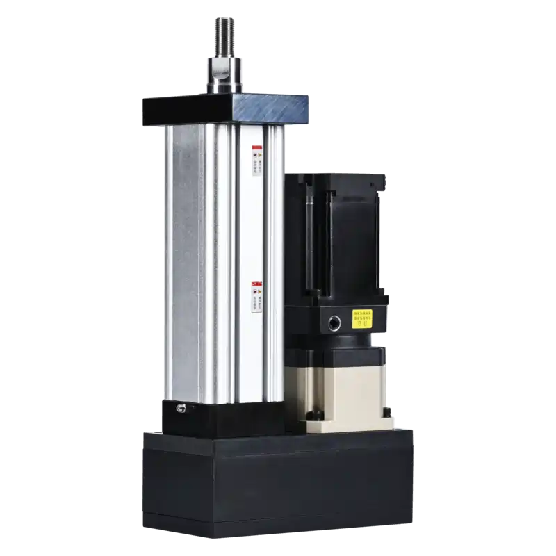
Mounting Configurations
Front Flange
Front-face flange mounting for through-panel or fixed-frame installation. The most common orientation for press and assembly applications.
StandardRear Flange
Rear-face flange mounting when the cylinder body extends through the mounting surface. Suitable for compact axial envelopes.
StandardFoot / Trunnion
Side-foot or trunnion mounting for pivoting or articulated installations. Common in testing fixtures and adjustable tooling.
OptionalCustom Interface
Special flanges, rod-end adaptations, or modified port locations. Specify at ordering — engineering confirms compatibility.
CustomServo Control, Feedback & Fieldbus Integration
The JRDG cylinder body is mechanically compatible with servo drive and controller ecosystems. Communication protocols and control features are attributes of the drive/controller, not the cylinder itself.
Servo Drive Compatibility
The cylinder accepts standard servo motor interfaces. Drive selection determines current capacity, control modes (position, velocity, torque), and tuning parameters.
Feedback Options
Motor-mounted encoders provide position feedback. Optional external linear feedback (e.g., linear scale) can be specified for applications requiring direct rod position measurement.
Controller Integration
Compatible with PLC, motion controller, and industrial PC environments through standard servo drive interfaces. Fieldbus selection (EtherCAT, PROFINET, etc.) is determined by the drive/controller.
Eight Critical Engineering Considerations
Review each boundary before final selection. These determine whether a JRDG configuration will perform reliably in your application.
Side Load
Radial loads on the output rod accelerate wear and reduce life. Keep side loads within limits; use external guides for significant lateral forces.
Buckling
Long strokes in compression are susceptible to column buckling. Critical load depends on rod diameter, stroke, mounting, and end conditions.
Impact Loading
Sudden stops or collisions generate peak forces far exceeding rated thrust. Use programmable deceleration and mechanical stops to protect screw and drive.
Continuous Duty / Thermal
High duty cycles generate heat in motor, drive, and screw. Continuous 24/7 operation requires thermal verification and may need derating or cooling.
Speed × Load
Maximum speed and maximum force are not simultaneously available. The force-speed envelope is configuration-specific — verify your operating point.
System Accuracy
Accuracy, repeatability, and resolution are separate parameters affected by screw grade, feedback, drive tuning, and frame rigidity. Specify each independently.
Vertical Safety
Vertical mounting with downward load requires fail-safe consideration. Brakes, counterbalance, or mechanical locks prevent unintended descent on power loss.
Environment
Dust, moisture, chemicals, and temperature affect seals, lubrication, and motor life. IP rating and environmental protection must be specified for the application.
Where JRDG Excels
Common application categories where JRDG servo electric cylinders are well-suited or conditionally suited. These are application-fit descriptions, not case-study claims.
Precision Press Fitting & Assembly
Controlled-force insertion of bearings, bushings, pins, and connectors. Programmable force-displacement profiles enable quality monitoring and press-fit verification with traceable records.
Positioning, Feeding & Format Adjustment
Precise linear positioning for indexing, feeding, and transfer operations. Servo control enables multi-point positioning with adjustable speed and acceleration — replace manual adjustment with stored recipes.
Cyclic Testing & Inspection
Fatigue testing, life testing, and load simulation with repeatable cyclic motion and force profiles. Data logging enables test result traceability and waveform fidelity.
Forming, Bending & Stamping
Light forming, embossing, bending, and punching where force and stroke are within configuration limits. High-impact or high-tonnage forming requires engineering review — severe shock may be better served by hydraulic or flywheel systems.
Lifting, Lowering & Tilting
Vertical lifting and hoisting applications. Requires fail-safe braking, buckling analysis, and duty-cycle verification — not recommended for unsupported long-stroke lifting or personnel lifting without independent safety assessment.
Clamping & Holding
Workholding and fixture clamping with controlled force. Sustained static clamping may require brake or mechanical lock to avoid continuous motor torque and thermal buildup.
Automotive & EV
- Engine component press-fit (cylinder head, liners, oil seals)
- Steering gear assembly (gears, pin shafts)
- Driveshaft & gearbox press fitting
- Brake disc component assembly
Motor & Rotating Machinery
- Micro-motor assembly (spindle, housing)
- Motor bearing press-fit
- Rotor and stator insertion
Electronics & Battery
- PCB component press-fit (connectors, pins)
- Electronic parts insertion
- Battery cell assembly & stacking
Home Appliance
- Appliance parts press fitting
- Riveting and clinching operations
- Motor and pump assembly
General Machinery
- Mechanical parts press-fit
- Automated assembly lines
- Wear-part life & fatigue testing
Precision Force Control
- Any application requiring CNC-controlled press force & displacement
- Quality-monitored assembly with traceable force-displacement curves
JRDG Servo Electric Cylinder FAQ
Direct answers for product comparison, preliminary selection, and quotation scope. Structured for AI search and engineering reference.
What is a JRDG servo electric cylinder?
The JRDG is a single-stage, screw-driven electromechanical linear actuator. A servo motor rotates a ball screw or roller screw through an inline coupling or parallel belt transmission, converting rotary motion into controlled linear force and position. Encoder and drive close the position, speed, and torque loops.
Can a JRDG electric cylinder replace my pneumatic cylinder?
Yes, when you need programmable multi-position motion, stable speed, recipe changeover, energy control, or motion traceability. Compare the whole system — not just actuator price. Simple two-position high-speed applications where compressed air is already efficient may remain better served by pneumatics.
What is the difference between direct and parallel drive?
Direct drive mounts the motor in-line with the cylinder axis for maximum torsional rigidity and compact radial envelope, but longer overall length. Parallel drive mounts the motor beside the cylinder via belt or gear, reducing overall length while widening the footprint. Both share the same cylinder body and screw assembly.
Can maximum thrust and maximum speed be achieved simultaneously?
No. Screw lead, motor torque-speed characteristics, drive current, voltage, and thermal duty create a configuration-specific force-speed envelope. The JRDG publishes observed ranges; your actual operating point must be verified against the selected configuration envelope. Never assume catalog maxima are simultaneously achievable.
What data do I need to select a JRDG model?
Provide process task, required force vs time, moving mass, stroke, approach/working/return speeds, acceleration, dwell, cycle rate, mounting orientation, side load, environment, motor/drive preference, and required accuracy/repeatability. Our engineering team converts these into a verified configuration with life, buckling, thermal, and force-speed checks.
Is a JRDG electric cylinder the same as a servo press?
No. The JRDG is the mechanical linear axis. A complete servo press requires matched motor and drive, force sensing (load cell), process controller, machine frame, tooling, safety controls, and validation. We can supply the cylinder alone, a matched motor-drive package, or collaborate on a complete engineered system.
Which JRDG size models are available?
Loaded size models include JRDG44, 53, 60, 75, 95, 110, 138, 170, 220, and 265 — spanning 0.67 to 382 kN observed thrust and up to 2500 mm stroke. JRDG205 and JRDG295 are in the registry but performance records are pending publication. Contact engineering for configurations beyond the loaded model set.
When should I NOT use an electric cylinder?
Retain pneumatic actuation when only two end positions are needed, cost is the sole driver, and compressed air is already efficient. Retain hydraulic when very high force density, severe shock tolerance, or sustained heavy duty dominates and clean data-rich motion is secondary. For uncontrolled impact, severe side load without guidance, or safety-critical personnel lifting, always require engineering review before selecting any actuator technology.
Technical Resources & Evidence
Documentation and manufacturing evidence for the JRDG family. Request per-model or per-configuration resources as needed.
Product Datasheet
Per-size-model specification sheets with configuration tables
Request per ModelDimension Drawings
2D dimension drawings and 3D CAD models per configuration
Request per ConfigSelection Guide
Engineering selection methodology and calculation worksheets
Available on RequestManufacturing Evidence
Factory, assembly, inspection, and testing documentation
Evidence Pack in PrepTest Reports
Performance verification and quality test records
Available on RequestCompliance Docs
ISO certification and material certificates
ISO 9001:2015Ready to Spec Your JRDG?
Get an engineering-verified configuration for your application. Our team will match size model, drive arrangement, screw lead, and motor to your requirements.