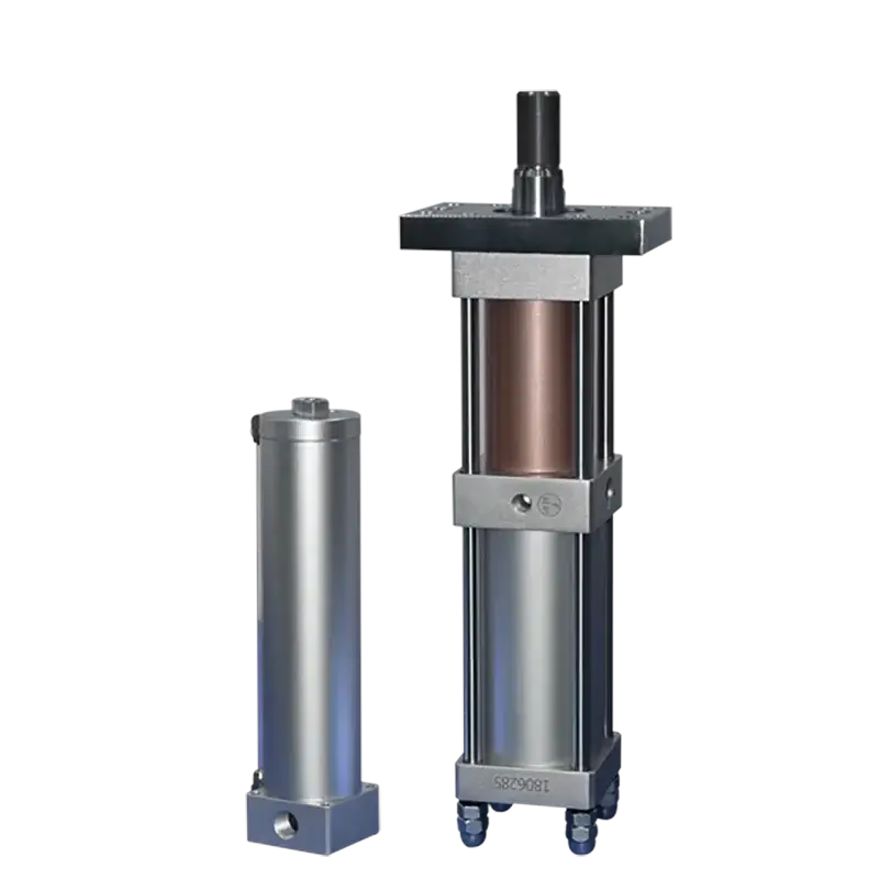
JRAB Split Oil-Reservoir Hydro-Pneumatic Cylinder
An extended model of the JRAA horizontal platform. The oil reservoir is separated from the cylinder body and mounted vertically, while the force-output section connects via a high-pressure oil hose — enabling any-angle installation for space-constrained equipment.
Why Split Oil-Reservoir?
The JRAB separates the oil reservoir from the booster cylinder body. The reservoir mounts vertically; the force-output section connects via a high-pressure oil hose and can be installed at any angle — solving layout challenges in compact equipment.
Split-Type Structure
The oil reservoir is separated from the cylinder body and installed vertically, decoupling reservoir position from force-output direction.
Any-Angle Mounting
The force-output section supports horizontal, vertical, inverted, or any-angle installation — ideal for equipment requiring flexible force direction.
Oil Hose Connection
The force-output section and reservoir are connected by a high-pressure oil hose, solving installation layout challenges in compact spaces.
Pre-Press Family
Belongs to the pre-press booster cylinder family, with both pre-press stroke and pressure stroke for two-stage force output.
Moderate Frequency
Suited for applications where operating frequency is not extremely high but mounting angle and space constraints are demanding.
Customizable
Customizable for special mounting methods or non-standard application requirements.
Structural Concept
The oil reservoir is separated from the booster cylinder body and installed vertically. The force-output section is connected to the reservoir through a high-pressure oil hose and can be mounted horizontally, vertically, inverted, or at other angles as required on site.
Reservoir — Vertical Only
The oil reservoir must be installed vertically to maintain proper oil condition and stable operation.
Force Section — Any Angle
The force-output section can be mounted horizontally, vertically, inverted, or at any angle the application requires.
Hose — Flexible Bridge
The high-pressure oil hose connects the two sections. Hose length, bending radius, and secure fixing must be considered during layout.
Operating Conditions
Pneumatic & Fluid
| Power source | 4-7 kg/cm² clean compressed air |
| Reference air pressure | 6 kg/cm² |
| Working temperature | 0-60°C |
| Hydraulic oil | ISO VG46 or ISO VG68 anti-wear hydraulic oil |
| Recommended air supply | An air reservoir is recommended between the booster cylinder and the air preparation unit to ensure stable air supply |
Structural
| Structure Type | Split / separate oil-reservoir |
| Reservoir Mounting | Vertical (mandatory) |
| Force-Output Mounting | Any angle (horizontal, vertical, inverted) |
| Connection | High-pressure oil hose |
| Actuation Type | Double-acting (pre-press + boost) |
| Family | Pre-press booster cylinder |
Note: The current materials do not provide a complete JRAB dimension table or theoretical output force table. Contact our engineering team for model-specific dimensions and force data.
Pneumatic Circuit Diagram
The JRAB uses two valves (DT1/DT2) to control four air ports (A/B/C/D). DT1 controls the pre-press cylinder; DT2 controls the booster section. An air preparation unit (E) treats the supply air.
Operation Sequence (4-Step Cycle)
The JRAB runs a standard pre-press four-step cycle. Ports A/B control the pre-press piston; ports C/D control the booster piston. The split reservoir design does not change the cycle logic.
Return / Home
Ports A and C are supplied with air. The booster cylinder stays in the return position — pre-press piston up, booster piston retracted.
Pre-press Approach
Port B is supplied, port A exhausts. Compressed air acts on the reservoir oil surface, driving the pre-press piston until the tooling contacts the workpiece.
Boost Forming
Port B holds; port D is supplied, port C exhausts. The booster piston compresses the hydraulic oil, maintaining high force for forming the product.
Return & Reset
Port C is supplied, port D exhausts. After the booster returns, port A is supplied and port B exhausts. The pre-press piston returns; oil flows back to the reservoir. Cycle complete.
Mounting Flexibility
The JRAB's defining advantage: the force-output section installs at any angle, while the oil reservoir mounts vertically nearby. The high-pressure oil hose bridges the two, giving you freedom to place each component where the machine layout demands.
Vertical (Rod-Down)
Force-output section mounted rod-down, with the reservoir installed vertically alongside. Classic top-down pressing configuration.
Horizontal (Rod-Forward)
Force-output section mounted horizontally for side-press applications. Reservoir stands vertically nearby, connected by oil hose.
Inverted (Rod-Up)
Force-output section mounted rod-up for bottom-up pressing or lifting. The reservoir still mounts vertically, connected via hose.
Any Angle (Custom)
Force-output section at any custom angle for specialized equipment. Specify your mounting requirements before ordering for tailored production.
Build Your Model Number
The JRAB model code has five segments: JRAB - oil cylinder bore - total stroke - pressure stroke - output tonnage. Configure below to see your model code update in real time.
Configuration Summary
Selection Guide
When selecting a JRAB model, consider these seven key parameters. Our engineering team will help you match the right configuration to your application.
Oil Cylinder Bore
Required bore diameter (mm) based on force and speed requirements.
Total Stroke
Required total stroke (mm) to reach the workpiece from home position.
Pressure Stroke
Required high-force pressure stroke (mm) for the forming / pressing operation.
Output Tonnage
Required boosted output force (tons) at the reference air pressure of 6 kg/cm².
Operating Frequency
Required cycle frequency (cycles/min). JRAB is suited for moderate-frequency applications.
Return / Lifting Force
Required return force or lifting force (kgf) to retract the piston and tooling weight.
Mounting Angle & Space
Mounting angle, oil reservoir position, and available installation space — the critical parameters for JRAB's split-type layout. Specify the force-output direction and reservoir placement constraints.
Applications
The JRAB is ideal for non-standard automation equipment with limited installation space or flexible force-direction requirements. Below are typical processes and industries served.
Typical Processes
Industries & Equipment
Maintenance Notes
Proper maintenance ensures stable output force and long service life. Pay special attention to oil level and air quality in the split-reservoir design.
Use Correct Hydraulic Oil
Use ISO VG46 or ISO VG68 anti-wear hydraulic oil only. Do not replace hydraulic oil with other media — incorrect fluid will damage seals and reduce boost performance.
Monitor Oil Level
Check the reservoir oil level regularly. Oil below the lower limit may cause insufficient pressure or stroke. The split reservoir design makes the oil level easily visible.
Do Not Overfill
Do not fill oil above the upper limit. Excessive oil level may cause hydraulic oil overflow or discharge during operation. Maintain oil between the min and max marks.
Clean & Stable Air Supply
For more stable output force, ensure clean and stable compressed air. An air reservoir between the booster cylinder and the air preparation unit is recommended to buffer pressure fluctuations.
Resources & Downloads
JRAB Product Catalog (PDF)
Complete specifications, model selection guide, ordering information
Operation & Maintenance Manual
Installation, oil filling, hose routing, maintenance intervals
CAD Drawings (DWG / STEP)
2D/3D models for your specific bore, stroke, and mounting configuration
Pneumatic Circuit Diagram
Air circuit schematic with port definitions and valve specifications
Ready to Configure Your JRAB?
Send us your required tonnage, stroke, mounting angle, and available installation space. Our engineering team will reply with a quotation and dimension sheet within 24 hours.