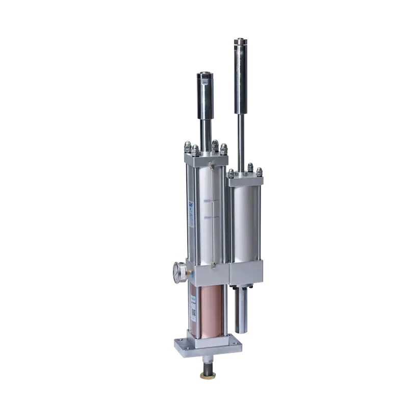
JRD Dual-Adjustable Hydro-Pneumatic Booster Cylinder
Independently set the total approach travel and the high-force power stroke for tooling-height and working-depth changes on the same press platform.
Technical Specifications
Performance
| Output Force Range | 1–40 tons |
| Standard Total Stroke Options | 50 / 100 / 150 / 200 / 300 / 400 mm |
| Power Stroke Options | 5 / 10 / 15 / 20 mm |
| Operating Speed | 50–400 mm/s |
| Cycle Frequency | 25–45 cycles/min |
Pneumatic & Fluid
| Operating Pressure | 4–7 kgf/cm² compressed air |
| Actuation Type | Double-acting |
| Hydraulic Fluid | VG68# anti-wear hydraulic oil |
| Air Port Thread | ZG3/8" – ZG1" (model dependent) |
| Working Temperature | 0–60 °C |
Mechanical
| Bore Sizes | ∅63, 80, 100, 125, 160 mm |
| Mounting Orientation | Vertical, standard orientation |
| Total-Stroke Adjustment | 50 / 100 / 150 / 200 mm (A code) |
| Power-Stroke Adjustment | 5 / 10 / 15 / 20 mm (B code) |
| Pre-press Stroke Tolerance | +1.00 / 0.00 mm |
| Power Stroke Tolerance | +0.20 / 0.00 mm |
| Custom Options | Special strokes and interfaces on review |
Force vs. Displacement Profile
The JRD delivers two distinct force regimes in one cycle. Fast approach uses low air force for speed; the boost phase triggers high-force oil intensification over the final millimeters.
The curve is a conceptual sequence diagram, not a scaled force or displacement chart. Use the catalog force table and configuration-specific dimensions for engineering decisions.
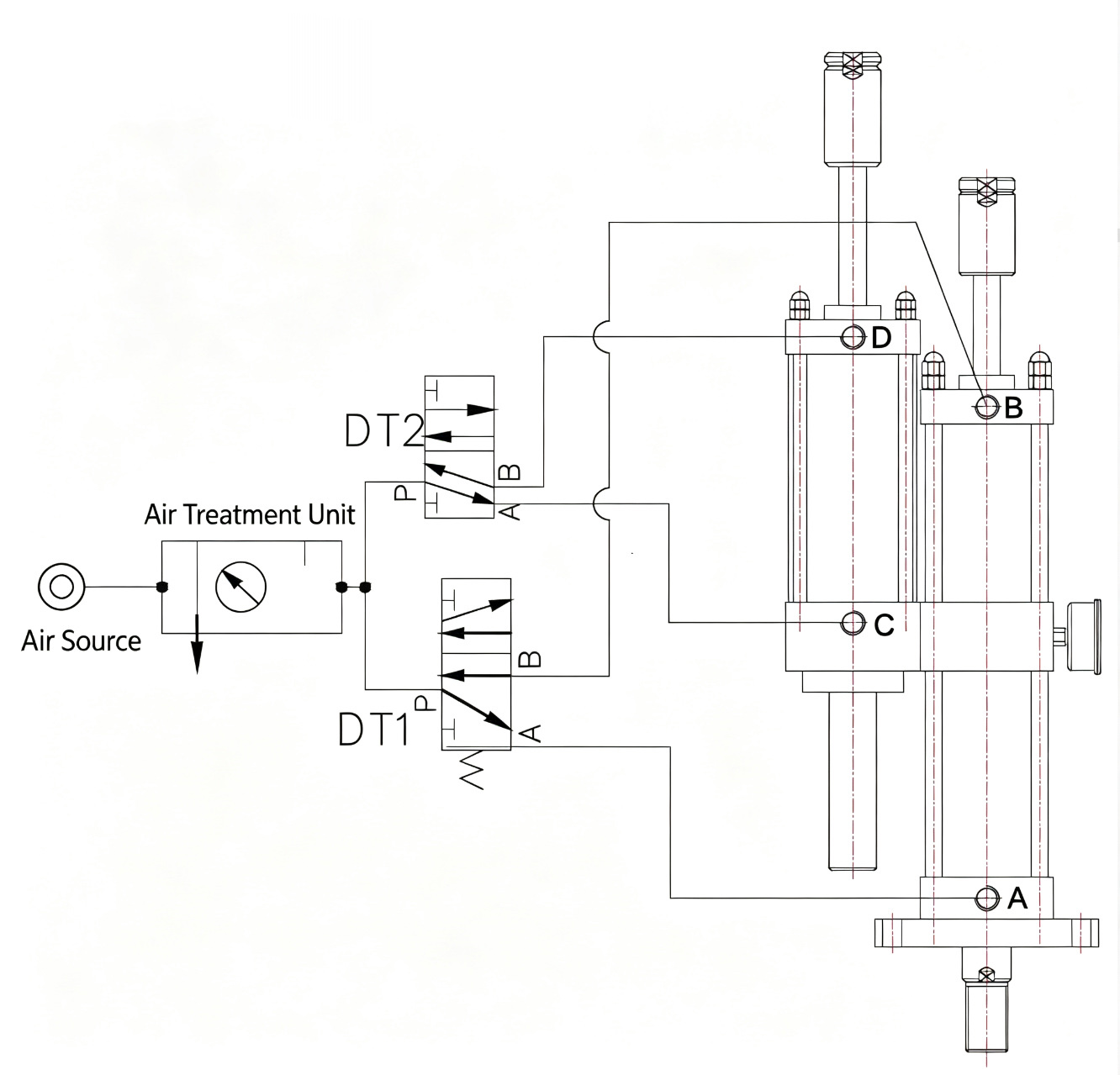
Pneumatic Circuit Diagram
The catalog circuit routes treated compressed air through DT1 and DT2. DT1 controls the cylinder section through ports A and B; DT2 controls the booster section through ports a and b.
Mounting Configurations
JRD is designed for standard vertical installation. Provide access to both the A total-stroke adjustment and B power-stroke adjustment, then lock both settings before production.
Vertical Mount (JRD Standard)
The JRD catalog identifies vertical mounting as the standard installation. Confirm load alignment and machine interfaces during engineering review.
Dual-Adjustment Access
Reserve service space for the rear A adjustment and power-stroke B adjustment so setup can be completed and verified safely.
Special Configuration Review
The manufacturer accepts special customization requests. Non-standard strokes, interfaces, or mounting conditions require written engineering confirmation.
Installation Dimensions
Catalog-supported bore and force combinations. Overall dimension N depends on the A total-stroke adjustment; dimension O depends on the B power-stroke adjustment.
| Bore | Catalog force classes | Adjustable total stroke (A) | Adjustable power stroke (B) | Air-port thread range |
|---|---|---|---|---|
| ∅63 mm | 1 / 3 / 5 / 10 T | 50 / 100 / 150 / 200 mm | 5 / 10 / 15 / 20 mm | ZG3/8" – ZG1/2" |
| ∅80 mm | 3 / 5 / 10 / 15 T | 50 / 100 / 150 / 200 mm | 5 / 10 / 15 / 20 mm | ZG3/8" – ZG1/2" |
| ∅100 mm | 5 / 10 / 15 / 20 T | 50 / 100 / 150 / 200 mm | 5 / 10 / 15 / 20 mm | ZG3/8" – ZG3/4" |
| ∅125 mm | 10 / 15 / 20 / 30 T | 50 / 100 / 150 / 200 mm | 5 / 10 / 15 / 20 mm | ZG1/2" – ZG3/4" |
| ∅160 mm | 15 / 20 / 30 / 40 T | 50 / 100 / 150 / 200 mm | 5 / 10 / 15 / 20 mm | ZG1/2" – ZG1" |
The catalog defines fixed dimensions A–K, M, P and Q by bore/force combination. Dimension N changes with the selected A adjustment and dimension O changes with the selected B adjustment. Request verification of the complete configuration-specific dimension set before releasing machine drawings.
When the JRD Adjustment Architecture Fits
JRD is differentiated by two independent adjustments. Selection still requires the operating load, strokes, frequency, return force, and standard mounting condition to be checked together.
Both working positions change
Use the A setting for total travel and the B setting for high-force working travel when both dimensions must be tuned independently.
One or both strokes are fixed
A dual-adjustable JRD may add unnecessary setup capability. Ask engineering to compare the required motion with the available JiuRong series before selecting.
Build Your Model Number
Choose a catalog-listed combination and build the JR-D code. The displayed force is looked up from the catalog table for the selected bore, force class, and whole-number supply pressure.
Catalog values are theoretical. The source recommends that actual output not exceed 50% of the tabulated value to avoid reducing operating speed. Engineering verification remains required.
Typical Applications
The catalog lists extrusion, bending, punching, forming, riveting, trimming, assembly, and printing. Final suitability depends on the required force, motion, frequency, return force, and installation.
Resources & Downloads
JRD Selection Data
Request verified model, force, stroke, and dimension information for your configuration.
Circuit & Sequence Review
Ask engineering to review DT1/DT2 control, ports, and the four-step operating sequence.
Configuration Review
Submit application inputs before relying on a model code or installation envelope.
Ready to Configure Your JRD?
Send the required bore, pre-stroke, power stroke, output tonnage, operating frequency, return force, and mounting requirement for engineering selection and quotation.