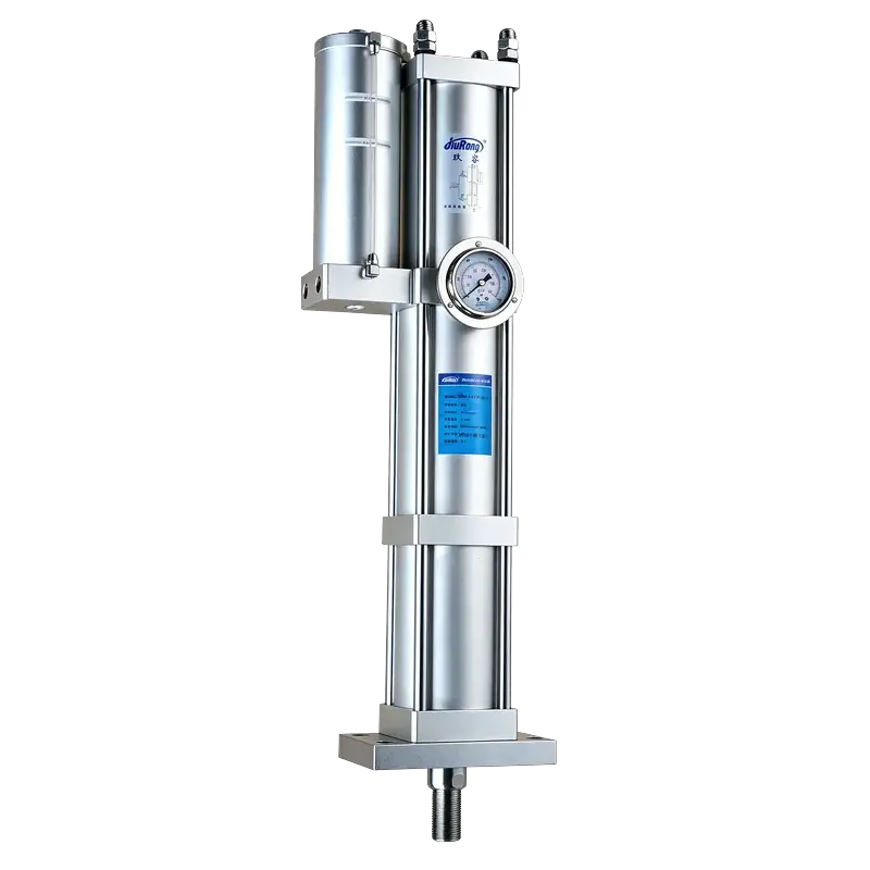
JRM High-Speed Hydro-Pneumatic Booster Cylinder
More strokes per shift. The JRM is JiuRong's throughput-optimised booster cylinder — a slender body with oil-gas isolation delivers 30–50% faster cycles than the standard JRA, while the integrated protective cover keeps maintenance stops off your schedule.
Why Speed Is the Throughput Multiplier
When the press is the bottleneck, every fraction of a second per cycle compounds across thousands of strokes per shift. The JRM is not a standard cylinder with a "fast" label — it is purpose-built where three engineering changes work together to cut cycle time.
Cycle-Time Comparison: JRA Standard vs JRM High-Speed
Speed improvement range per JiuRong catalog data (30% per catalog, 50% per gallery). Actual cycle-time reduction depends on stroke length, operating pressure, and force setting. Confirm with engineering for your specific parameters.
Slender Body
The elongated, narrow profile reduces moving mass, enabling faster acceleration on approach and quicker retraction after each press stroke.
Oil-Gas Isolation
Separating the hydraulic oil circuit from the pneumatic circuit increases return and lifting force — the cylinder retracts faster, shortening the non-productive portion of every cycle.
Integrated Protective Cover
Shields the cylinder body from shop-floor contaminants, reducing wear-related maintenance stops that erode throughput in high-cycle environments.
Operating Principle
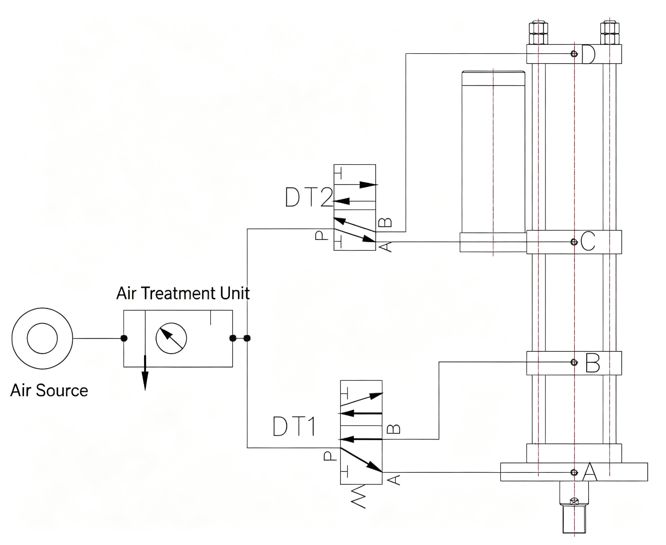
A two-stage cycle — fast pneumatic approach followed by hydro-pneumatic boost — controlled by dual 5-port solenoid valves on a three-port circuit (A / B / C).
Force vs. Displacement
-
1
Fast Approach — DT1 ON
Solenoid DT1 energises. Air pressure acts on the oil reservoir, driving the piston down at low force through the full approach stroke. The slender body minimises inertia for rapid traverse.
-
2
Boost — DT1 + DT2 ON
The rod meets resistance. DT1 holds and DT2 energises, routing air to the boost chamber. Pascal's principle multiplies force through the oil column, delivering high pressing force over the short power stroke.
-
3
Pressure Release — DT2 OFF
After holding pressure as needed, DT2 de-energises. The boost chamber retracts and the cylinder releases pressure before return.
-
4
Fast Return — DT1 OFF
DT1 de-energises. Oil-gas isolation provides increased return force, snapping the piston back quickly. Oil returns to the reservoir — one cycle complete.
Three-Port Pneumatic Circuit (A / B / C)
Technical Specifications
Performance
| Actuation Type | Double-acting |
| High Pressure Output | 1–40 tons |
| Operating Speed | 50–400 mm/s |
| Operating Frequency | 25–45 cycles/min |
| Speed Advantage | 30–50% faster than JRA |
Fluid & Pressure
| Operating Pressure | 4–7 kgf/cm² (compressed air) |
| Hydraulic Medium | ISO VG68 anti-wear oil |
| Oil Cylinder Proof | 120 kgf/cm² |
| Air Cylinder Proof | 30 kgf/cm² |
| Working Temperature | 0–60 °C |
Mechanical
| Bore Sizes | ∅80, 100, 125, 150, 160 mm |
| Total Stroke | 50–400 mm |
| Power Stroke | 5 / 10 / 15 / 20 mm |
| Mounting Type | Vertical (standard) |
| Protective Cover | Integrated (standard) |
Installation Dimensions
All dimensions in millimetres. Select a bore size to view dimensions for each tonnage class. N = overall length at the indicated power stroke (5 / 10 / 15 / 20 mm).
∅80 mm Bore — Dimensions by Tonnage
| Ton | A | B | C | D | E | F (Air) | G (Rear) | H | I | J | K | L | M (Thread) | N (5mm) | N (10mm) | N (15mm) | N (20mm) | O | P |
|---|---|---|---|---|---|---|---|---|---|---|---|---|---|---|---|---|---|---|---|
| 5T | 160 | 100 | 132 | 65 | 19 | ZG3/8" | ZG3/8" | 20 3/8 | 50 | 75 | 35 | 22 | M30x1.5 | 432 | 512 | 592 | 672 | 70 | 95 |
| 10T | 180 | 132 | 65 | 19 | 24 | ZG3/8" | ZG3/8" | 20 3/8 | 50 | 75 | 35 | 22 | M30x1.5 | 529 | 621 | 713 | 805 | 70 | 95 |
| 15T | 190 | 118 | 155 | 65 | 22 | ZG3/8" | ZG1/2" | 20 3/8 | 50 | 90 | 40 | 25 | M30x1.5 | 515 | 605 | 695 | 785 | 90 | 110 |
∅100 mm Bore — Dimensions by Tonnage
| Ton | A | B | C | D | E | F (Air) | G (Rear) | H | I | J | K | L | M (Thread) | N (5mm) | N (10mm) | N (15mm) | N (20mm) | O | P |
|---|---|---|---|---|---|---|---|---|---|---|---|---|---|---|---|---|---|---|---|
| 5T | 190 | 145 | 190 | 85 | 28 | ZG1/2" | ZG1/2" | 26 1/2 | 85 | 110 | 60 | 35 | M40x2 | 615 | 710 | 805 | 900 | 110 | 140 |
| 10T | 225 | 110 | 25 | 241 | 12 | ZG3/8" | ZG1/2" | 27 1/2 | 50 | 75 | 35 | 25 | M30x1.5 | 600 | 710 | 820 | 930 | 90 | 110 |
| 15T | 235 | 165 | 200 | 100 | 32 | ZG1/2" | ZG3/4" | 300 | 110 | 120 | 60 | 40 | M42x2 | 672 | 780 | 888 | 996 | 140 | 160 |
∅125 mm Bore — Dimensions by Tonnage
| Ton | A | B | C | D | E | F (Air) | G (Rear) | H | I | J | K | L | M (Thread) | N (5mm) | N (10mm) | N (15mm) | N (20mm) | O | P |
|---|---|---|---|---|---|---|---|---|---|---|---|---|---|---|---|---|---|---|---|
| 10T | 200 | 200 | 260 | 120 | 38 | ZG3/4" | ZG1" | 380 | 160 | 160 | 100 | 60 | M64x2 | 914 | 1050 | 1186 | 1322 | 200 | 240 |
| 15T | 290 | 145 | 190 | 85 | 28 | ZG1/2" | ZG3/4" | 26 3/4 | 85 | 110 | 60 | 35 | M40x2 | 672 | 780 | 888 | 996 | 110 | 140 |
| 20T | 300 | 220 | 280 | 140 | 42 | ZG3/4" | ZG1" | 420 | 160 | 195 | 100 | 60 | M64x2 | 977 | 1120 | 1263 | 1406 | 200 | 260 |
∅150 mm Bore — Dimensions by Tonnage
| Ton | A | B | C | D | E | F (Air) | G (Rear) | H | I | J | K | L | M (Thread) | N (5mm) | N (10mm) | N (15mm) | N (20mm) | O | P |
|---|---|---|---|---|---|---|---|---|---|---|---|---|---|---|---|---|---|---|---|
| 20T | 290 | 200 | 260 | 120 | 32 | ZG3/4" | ZG1" | 26 3/4 | 120 | 135 | 75 | 50 | M48x2 | 868 | 985 | 1102 | 1219 | 150 | 190 |
| 30T | 300 | 220 | 280 | 140 | 38 | ZG1" | ZG1 1/4" | 330 | 160 | 160 | 100 | 60 | M56x2 | 1009 | 1140 | 1271 | 1402 | 200 | 240 |
| 40T | 360 | 260 | 340 | 160 | 42 | ZG1 1/4" | ZG1 1/2" | 420 | 200 | 195 | 130 | 75 | M64x2 | 1220 | 1380 | 1540 | 1700 | 260 | 310 |
∅160 mm Bore — Dimensions by Tonnage
| Ton | A | B | C | D | E | F (Air) | G (Rear) | H | I | J | K | L | M (Thread) | N (5mm) | N (10mm) | N (15mm) | N (20mm) | O | P |
|---|---|---|---|---|---|---|---|---|---|---|---|---|---|---|---|---|---|---|---|
| 20T | 300 | 220 | 280 | 140 | 38 | ZG1" | ZG1 1/4" | 330 | 160 | 160 | 100 | 60 | M56x2 | 1009 | 1140 | 1271 | 1402 | 200 | 240 |
| 30T | 360 | 260 | 340 | 160 | 42 | ZG1 1/4" | ZG1 1/2" | 420 | 200 | 195 | 130 | 75 | M64x2 | 1220 | 1380 | 1540 | 1700 | 260 | 310 |
| 40T | 390 | 290 | 380 | 180 | 50 | ZG1 1/2" | ZG2" | 510 | 240 | 240 | 160 | 90 | M80x3 | 1460 | 1650 | 1840 | 2030 | 307 | 367 |
F = side air port thread; G = rear air port thread. Standard data; custom dimensions available on request.
Theoretical Output Force vs. Air Pressure
Theoretical high-pressure force in kgf at 4–7 kgf/cm² supply pressure. Values shown for 80–150 mm bores; 160 mm force data per engineering confirmation.
| Bore | Ton | 4 kgf/cm² | 5 kgf/cm² | 6 kgf/cm² | 7 kgf/cm² |
|---|---|---|---|---|---|
| ∅80 mm | 5T | 2,800 | 3,500 | 4,200 | 4,900 |
| ∅80 mm | 10T | 5,600 | 7,000 | 8,400 | 9,800 |
| ∅80 mm | 15T | 8,400 | 10,500 | 12,600 | 14,700 |
| ∅100 mm | 5T | 4,500 | 5,625 | 6,750 | 7,875 |
| ∅100 mm | 10T | 9,000 | 11,250 | 13,500 | 15,750 |
| ∅100 mm | 15T | 13,500 | 16,875 | 20,250 | 23,625 |
| ∅125 mm | 10T | 9,375 | 11,719 | 14,063 | 16,406 |
| ∅125 mm | 15T | 14,063 | 17,578 | 21,094 | 24,609 |
| ∅125 mm | 20T | 18,750 | 23,438 | 28,125 | 32,813 |
| ∅150 mm | 20T | 12,000 | 15,000 | 18,000 | 21,000 |
| ∅150 mm | 30T | 18,000 | 22,500 | 27,000 | 31,500 |
| ∅150 mm | 40T | 24,000 | 30,000 | 36,000 | 42,000 |
Above are theoretical values. Actual output force should not exceed 50% of the listed values to preserve operating speed.
How to Select a JRM
Seven parameters to specify for an accurate quotation.
Oil Cylinder Bore
80 / 100 / 125 / 150 / 160 mm — determines the available tonnage range.
Total Stroke
50–400 mm approach travel. Longer strokes reduce cycles per minute.
Power Stroke
5 / 10 / 15 / 20 mm of high-force travel after workpiece contact.
Required Tonnage
1–40 T. Match to the pressing force your application demands.
Target Cycle Rate
25–45 cycles/min. State your strokes-per-shift target so we can confirm the speed advantage at your parameters.
Return Force
Required lifting / return force in kg — oil-gas isolation boosts this over standard designs.
Mounting
Vertical (standard) with integrated protective cover. Confirm clearance for the slender body profile.
Build Your Model Number
The JRM model code: JR-M-bore-total stroke-power stroke-tonnage. Configure below to see your model code update in real time.
Model Code Format
JR-M — JiuRong High-Speed series
Bore — oil cylinder bore in mm
Total Stroke — approach travel in mm
Power Stroke — high-force travel (5L/10L/15L/20L)
Tonnage — output force rating
Built for High-Volume Production
JRM earns its place when every stroke counts — high-cycle lines where the press sets the pace for the entire cell.
When JRM Is the Right Call
JRM is the speed-first variant. Choose it when cycle time limits throughput; choose a sibling when other requirements dominate.
Choose JRM when…
- Press cycle time is the bottleneck on your line
- You run high-volume production (automotive, consumer goods, electronics)
- You can quantify the value of additional strokes per shift
- Dusty or contaminated environment — the protective cover adds uptime
- Standard vertical mounting fits your machine
- Required force is within 1–40T, bore 80–160 mm
Consider a sibling when…
- Speed is not a constraint — JRA is the cost-effective default
- You need adjustable stroke — evaluate JRB / JRC
- You need single-stage direct force — choose JRE
- Installation length is the constraint — choose JRP parallel type
- You need programmable servo motion profiles
- Force below 5T — confirm availability with engineering
Frequently Asked Questions
What is the fastest JiuRong hydro-pneumatic booster cylinder?
How does JRM compare to JRA in speed?
What makes JRM faster than standard hydro-pneumatic cylinders?
Is JRM suitable for high-volume production?
What is the cycle rate of the JRM?
How much faster is JRM — 30% or 50%?
What is oil-gas isolation and how does it improve speed?
Does the protective cover affect cooling or performance?
What bore sizes are available in the JRM?
How do I calculate throughput improvement from switching to JRM?
Ready to Increase Your Press Throughput?
Send us your force, stroke, and target cycle rate — we'll confirm the JRM configuration and speed advantage for your application.