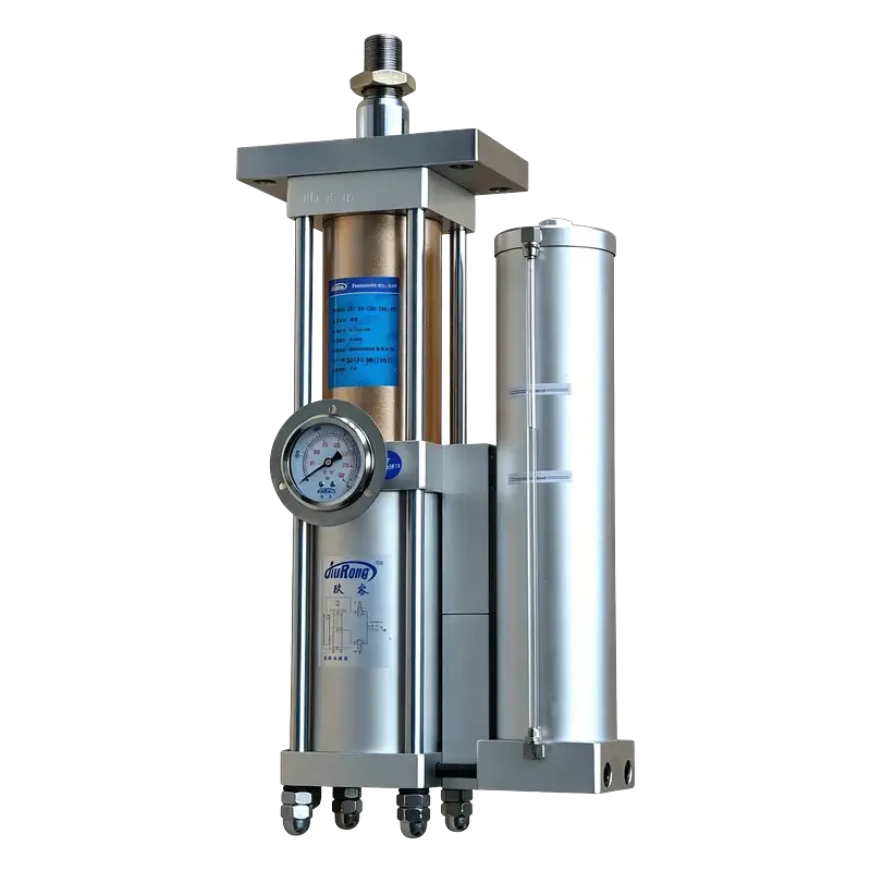
JRT Inverted Long-Stroke Hydro-Pneumatic Booster Cylinder
Upward pressing. Purpose-built inverted mounting.
The JRT is JiuRong's inverted-mount hydro-pneumatic booster cylinder — the rod extends upward, delivering 1–40 tons of high-pressure force from below the workpiece. Built on the same compact side-by-side architecture as the JRP, but with a purpose-designed inverted oil circuit and back-side port distribution. Not a flipped standard cylinder — an engineered upward-pressing solution.
Why Choose the JRT Inverted Series?
When your workpiece sits above the cylinder and force must push upward — bottom-up pressing, lifting-clamping, or die-lift applications — a standard downward-pressing cylinder cannot simply be flipped upside down. The oil reservoir, air passages, and return circuit depend on gravity. The JRT is purpose-engineered for inverted mounting: same compact side-by-side package as the JRP, but with an inverted oil circuit, back-side port layout, and upward rod extension.
JRP — Rod Down (Standard)
Cylinder above workpiece, rod extends downward. Gravity feeds oil to the booster.
JRT — Rod Up (Inverted)
Cylinder below workpiece, rod extends upward. Inverted oil circuit ensures reliable booster feed regardless of orientation.
Why Not Just Flip a Standard Cylinder?
A standard in-line or side-by-side cylinder relies on gravity to keep hydraulic oil at the booster intake. Flipping it upside down starves the booster, causes air entrainment, and leads to inconsistent force output — or complete failure. The JRT's internal oil passages, reservoir geometry, and return circuit are designed from the start for inverted operation, ensuring every cycle delivers rated tonnage upward.
Purpose-Built Upward Force
Rod extends upward to press, clamp, or lift from below — 1 to 40 tons of high-pressure output from standard 4–7 kgf/cm² shop air. No hydraulic power unit needed.
Compact Side-by-Side Package
Pneumatic and hydraulic cylinders run in parallel, keeping the axial envelope short — ideal for mounting under a worktable or platen where vertical headroom is limited.
Long Approach Stroke
Total strokes from 50 to 400 mm — the pneumatic approach stage extends upward quickly at low force, then the hydraulic power stroke engages for the final 5–20 mm at full tonnage.
Back-Side Port Distribution
Air ports are routed to the back face of the cylinder body, keeping the top (working) surface clean and unobstructed — easier plumbing when mounted under a fixture or table.
Fast Cycle Rate
25–45 cycles per minute with approach speeds up to 400 mm/s. The two-stage principle keeps air consumption low while maintaining throughput in automated lines.
JRT + JRP Matched Pair
For machines that press from both sides — top and bottom — the JRT (up) and JRP (down) share the same bore, stroke, and mounting footprint, simplifying frame design and spare parts.
How the JRT Works
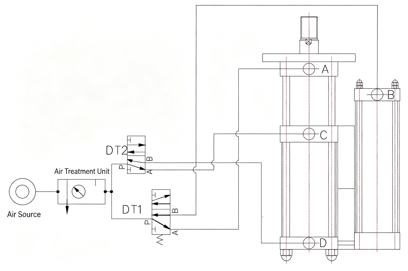
The JRT uses the same proven two-stage hydro-pneumatic principle as the JRP — a fast low-force pneumatic approach followed by a short high-force hydraulic power stroke — but the rod travels upward and the internal oil circuit is designed for inverted operation. Below: the force-displacement profile, the four-step upward cycle, and the pneumatic circuit.
Force vs. Displacement Profile
The rod extends upward on compressed air for the long approach stage. On workpiece contact, the hydraulic booster engages for the final 5–20 mm at full tonnage — pushing upward.
Four-Step Upward Cycle
-
01
Pneumatic Approach (Up)
Solenoid valve DT1 energizes. Shop air drives the piston upward at high speed (up to 400 mm/s) with low force — covering the full approach stroke with minimal air consumption.
-
02
Workpiece Contact
The upward-moving ram contacts the workpiece from below. Pneumatic force alone is insufficient for the operation — this triggers the hydraulic boost phase.
-
03
Hydraulic Power Stroke (Up)
Solenoid valve DT2 energizes. The booster piston pressurizes the hydraulic oil through the inverted oil circuit, multiplying force to rated tonnage (1–40T) for the final 5–20 mm of upward travel.
-
04
Pressure Release & Return (Down)
DT2 de-energizes to release hydraulic pressure, then DT1 de-energizes. The double-acting pneumatic return retracts the rod downward to home position — ready for the next cycle.
Pneumatic Circuit Diagram
Technical Specifications
Standard JRT series parameters. All models operate on standard shop air (4–7 kgf/cm²) and use VG68 anti-wear hydraulic fluid. The inverted oil circuit is designed for upward rod extension. Custom bore, stroke, and force configurations available on request.
Performance
- High-pressure output force
- 1–40 tons (nominal)
- Operating air pressure
- 4–7 kgf/cm² (0.4–0.7 MPa / 4–7 bar)
- Bore diameter
- Ø63 / 80 / 100 / 125 / 150 / 160 mm
- Total stroke (approach)
- 50 / 100 / 150 / 200 / 300 / 400 mm
- Power stroke (high-pressure)
- 5 / 10 / 15 / 20 mm
- Cycle rate
- 25–45 cycles / min
- Operating speed
- 50–400 mm/s
- Operating temperature
- 0–60 °C
Construction
- Actuation
- Double-acting
- Cylinder arrangement
- Side-by-side (pneumatic + hydraulic in parallel)
- Mounting orientation
- Inverted, rod-up (upward pressing)
- Oil circuit
- Inverted gravity-independent design
- Hydraulic fluid
- VG68 anti-wear hydraulic oil
- Hydraulic proof pressure
- 120 kgf/cm² (12 MPa)
- Pneumatic proof pressure
- 30 kgf/cm² (3 MPa)
- Rod treatment
- Hardened & ground alloy steel, chrome plated
Interface & Control
- Air supply port
- ZG3/8" – ZG1 1/2" (by model)
- Port distribution
- Back-side (rear face) routing
- Control valves
- Two 5/2-way solenoid valves (DT1, DT2)
- Control voltage
- DC 24 V (standard) / AC 220 V (optional)
- Rod end thread
- M30×1.5 – M100×3 (by model)
- Position sensing
- Magnetic reed / solid-state switches (optional)
- Noise level
- ≤ 75 dB(A) at 1 m
- Seals
- NBR / polyurethane, service-replaceable
Installation Dimensions
Standard JRT installation dimensions by bore size. Total length (N) varies with power stroke selection (5/10/15/20 mm). Port G indicates the back-side air port distribution dimension. All dimensions in mm unless noted. Custom configurations available on request.
Ø63 mm Bore — All Tonnage Options
| Ton | A | B | C | D | E | F (Port) | G (Back port) | H | I | J | K (Rod thread) | L | M | N (5mm) | N (10mm) | N (15mm) | N (20mm) | O | P | Q | R |
|---|---|---|---|---|---|---|---|---|---|---|---|---|---|---|---|---|---|---|---|---|---|
| 5T | 180 | 150 | 132 | 227.5 | 14 | ZG3/8" | 345 | 35 | 35 | 22 | M30x1.5 | 117 | 130 | 369 | 454 | 539 | 624 | 75 | 95 | 100 | 130 |
| 10T | 160 | 132 | 122 | 227.5 | 14 | ZG3/8" | 345 | 35 | 35 | 22 | M30x1.5 | 115 | 130 | 395 | 471 | 547 | 623 | 75 | 95 | 100 | 130 |
N = total installed length at the selected power stroke (5/10/15/20 mm). G = back-side air port distribution center distance. All other dimensions are constant regardless of power stroke. Scroll horizontally to view all columns on small screens.
Ø80 mm Bore — All Tonnage Options
| Ton | A | B | C | D | E | F (Port) | G (Back port) | H | I | J | K (Rod thread) | L | M | N (5mm) | N (10mm) | N (15mm) | N (20mm) | O | P | Q | R |
|---|---|---|---|---|---|---|---|---|---|---|---|---|---|---|---|---|---|---|---|---|---|
| 5T | 190 | 160 | 155 | 275 | 17 | ZG3/8" | 405 | 45 | 45 | 28 | M30x1.5 | 135 | 150 | 410 | 500 | 590 | 680 | 95 | 120 | 130 | 160 |
| 10T | 190 | 158 | 145 | 275 | 17 | ZG3/8" | 405 | 45 | 45 | 28 | M30x1.5 | 130 | 150 | 440 | 535 | 630 | 725 | 95 | 120 | 130 | 160 |
| 15T | 225 | 195 | 180 | 345 | 22 | ZG1/2" | 495 | 50 | 50 | 35 | M40x2 | 165 | 190 | 520 | 627 | 734 | 841 | 120 | 150 | 160 | 200 |
N = total installed length at the selected power stroke (5/10/15/20 mm). G = back-side air port distribution center distance. All other dimensions are constant regardless of power stroke. Scroll horizontally to view all columns on small screens.
Ø100 mm Bore — All Tonnage Options
| Ton | A | B | C | D | E | F (Port) | G (Back port) | H | I | J | K (Rod thread) | L | M | N (5mm) | N (10mm) | N (15mm) | N (20mm) | O | P | Q | R |
|---|---|---|---|---|---|---|---|---|---|---|---|---|---|---|---|---|---|---|---|---|---|
| 10T | 235 | 215 | 190 | 345 | 22 | ZG1/2" | 495 | 50 | 50 | 35 | M40x2 | 190 | 190 | 638 | 760 | 882 | 1004 | 140 | 180 | 190 | 235 |
| 15T | 200 | 190 | 170 | 310 | 22 | ZG1/2" | 455 | 50 | 50 | 35 | M40x2 | 165 | 175 | 625 | 750 | 875 | 1000 | 120 | 150 | 160 | 200 |
| 20T | 290 | 270 | 245 | 430 | 29 | ZG3/4" | 620 | 60 | 60 | 45 | M56x2 | 235 | 260 | 750 | 895 | 1040 | 1185 | 175 | 220 | 235 | 295 |
N = total installed length at the selected power stroke (5/10/15/20 mm). G = back-side air port distribution center distance. All other dimensions are constant regardless of power stroke. Scroll horizontally to view all columns on small screens.
Ø125 mm Bore — All Tonnage Options
| Ton | A | B | C | D | E | F (Port) | G (Back port) | H | I | J | K (Rod thread) | L | M | N (5mm) | N (10mm) | N (15mm) | N (20mm) | O | P | Q | R |
|---|---|---|---|---|---|---|---|---|---|---|---|---|---|---|---|---|---|---|---|---|---|
| 10T | 300 | 290 | 260 | 460 | 31 | ZG3/4" | 660 | 60 | 60 | 45 | M56x2 | 310 | 340 | 950 | 1135 | 1320 | 1505 | 240 | 300 | 320 | 400 |
| 15T | 290 | 270 | 245 | 430 | 29 | ZG3/4" | 620 | 60 | 60 | 45 | M56x2 | 235 | 260 | 750 | 895 | 1040 | 1185 | 175 | 220 | 235 | 295 |
| 20T | 300 | 290 | 260 | 460 | 31 | ZG3/4" | 660 | 60 | 60 | 45 | M56x2 | 310 | 340 | 950 | 1145 | 1340 | 1535 | 240 | 300 | 320 | 400 |
N = total installed length at the selected power stroke (5/10/15/20 mm). G = back-side air port distribution center distance. All other dimensions are constant regardless of power stroke. Scroll horizontally to view all columns on small screens.
Ø150 mm Bore — All Tonnage Options
| Ton | A | B | C | D | E | F (Port) | G (Back port) | H | I | J | K (Rod thread) | L | M | N (5mm) | N (10mm) | N (15mm) | N (20mm) | O | P | Q | R |
|---|---|---|---|---|---|---|---|---|---|---|---|---|---|---|---|---|---|---|---|---|---|
| 20T | 360 | 350 | 320 | 565 | 38 | ZG1" | 805 | 80 | 80 | 60 | M64x2 | 420 | 460 | 1260 | 1500 | 1740 | 1980 | 340 | 420 | 450 | 560 |
| 30T | 300 | 290 | 260 | 460 | 31 | ZG3/4" | 660 | 60 | 60 | 45 | M56x2 | 310 | 340 | 950 | 1145 | 1340 | 1535 | 240 | 300 | 320 | 400 |
| 40T | 360 | 350 | 320 | 565 | 38 | ZG1" | 805 | 80 | 80 | 60 | M64x2 | 420 | 460 | 1290 | 1540 | 1790 | 2040 | 340 | 440 | 470 | 590 |
N = total installed length at the selected power stroke (5/10/15/20 mm). G = back-side air port distribution center distance. All other dimensions are constant regardless of power stroke. Scroll horizontally to view all columns on small screens.
Ø160 mm Bore — All Tonnage Options
| Ton | A | B | C | D | E | F (Port) | G (Back port) | H | I | J | K (Rod thread) | L | M | N (5mm) | N (10mm) | N (15mm) | N (20mm) | O | P | Q | R |
|---|---|---|---|---|---|---|---|---|---|---|---|---|---|---|---|---|---|---|---|---|---|
| 30T | 390 | 380 | 350 | 620 | 43 | ZG1 1/4" | 883 | 100 | 100 | 70 | M80x3 | 468 | 510 | 1484 | 1764 | 2044 | 2324 | 400 | 510 | 540 | 680 |
| 40T | 420 | 410 | 380 | 680 | 46 | ZG1 1/2" | 963 | 110 | 110 | 80 | M100x3 | 536 | 585 | 1670 | 1990 | 2310 | 2630 | 460 | 580 | 620 | 780 |
N = total installed length at the selected power stroke (5/10/15/20 mm). G = back-side air port distribution center distance. All other dimensions are constant regardless of power stroke. Scroll horizontally to view all columns on small screens.
Theoretical Output Force vs. Air Pressure
Theoretical high-pressure output force in kgf at various supply pressures. Actual force varies with seal friction, back-pressure, and mechanical efficiency. For critical applications, apply a 0.85 derating factor or contact our engineering team.
| Bore | Nominal Force | 4 kgf/cm² | 5 kgf/cm² | 6 kgf/cm² | 7 kgf/cm² |
|---|---|---|---|---|---|
| Ø63 mm | 5T | 1,800 | 2,250 | 2,700 | 3,150 |
| Ø63 mm | 10T | 3,600 | 4,500 | 5,400 | 6,300 |
| Ø63 mm | 15T | 5,400 | 6,750 | 8,100 | 9,450 |
| Ø80 mm | 5T | 2,800 | 3,500 | 4,200 | 4,900 |
| Ø80 mm | 10T | 5,600 | 7,000 | 8,400 | 9,800 |
| Ø80 mm | 15T | 8,400 | 10,500 | 12,600 | 14,700 |
| Ø100 mm | 10T | 4,500 | 5,625 | 6,750 | 7,875 |
| Ø100 mm | 15T | 6,750 | 8,438 | 10,125 | 11,813 |
| Ø100 mm | 20T | 9,000 | 11,250 | 13,500 | 15,750 |
| Ø125 mm | 10T | 9,375 | 11,719 | 14,063 | 16,406 |
| Ø125 mm | 15T | 14,063 | 17,578 | 21,094 | 24,609 |
| Ø125 mm | 20T | 18,750 | 23,438 | 28,125 | 32,813 |
| Ø150 mm | 20T | 12,000 | 15,000 | 18,000 | 21,000 |
| Ø150 mm | 30T | 18,000 | 22,500 | 27,000 | 31,500 |
| Ø150 mm | 40T | 24,000 | 30,000 | 36,000 | 42,000 |
| Ø160 mm | 30T | 30,720 | 38,400 | 46,080 | 53,760 |
| Ø160 mm | 40T | 40,960 | 51,200 | 61,440 | 71,680 |
Values are theoretical at 100% efficiency. 1 kgf = 9.807 N. Nominal force ratings are at 6 kgf/cm² supply pressure.
JRT vs. JRP vs. JRA
The JRT, JRP, and JRA all deliver hydro-pneumatic force from standard shop air. The choice depends on pressing direction and machine envelope. The JRT is the only one purpose-engineered for upward (inverted) pressing.
JRT — Inverted Long-Stroke
Rod up — upward pressing
- Best for: Bottom-up pressing, die lift, upward clamping
- Purpose-built inverted oil circuit — not a flipped cylinder
- Side-by-side compact package, back-side ports
- 1–40T output, double-acting
- Mounts under worktable / platen
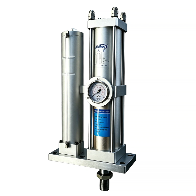
JRP — Compact Long-Stroke
Rod down — downward pressing
- Best for: Top-down pressing in short axial envelopes
- Same side-by-side architecture, downward direction
- Matches JRT bore / stroke / footprint for dual-action machines
- 1–40T output, double-acting
- Vertical mount, rod-down
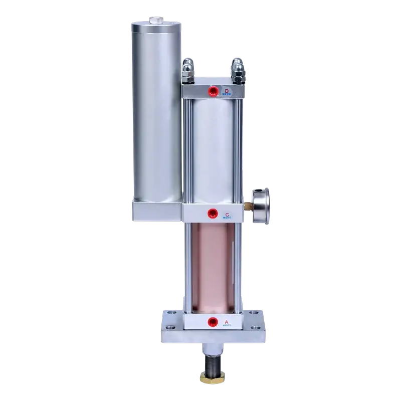
JRA — Standard Pre-Press
In-line, rod down
- Best for: Conventional top-down pressing with ample space
- In-line cylinder arrangement — longer axial envelope
- Widest bore and tonnage range (up to 100T)
- Most cost-effective when envelope allows
- Vertical or horizontal mount
How to Select a JRT
Follow these seven steps to configure the right JRT for your upward-pressing application. Our engineering team can review your requirements and confirm the selection.
-
1
Confirm Upward Pressing Direction
The JRT is for applications where the cylinder sits below the workpiece and the rod pushes upward. If your force direction is downward, choose the JRP (compact) or JRA (standard) instead. If you need both directions on the same station, use a matched JRT + JRP pair.
-
2
Determine Required Force
Calculate the pressing, forming, clamping, or lifting force your process requires. Select a nominal tonnage that provides at least 15% margin over the calculated requirement. Refer to the force table above for actual output at your shop air pressure.
-
3
Choose Bore Size
Bore determines the available tonnage options: Ø63 for 5–15T, Ø80 for 5–15T, Ø100 for 10–20T, Ø125 for 10–20T, Ø150 for 20–40T, Ø160 for 30–40T.
-
4
Set Approach Stroke
The total (approach) stroke is the upward travel from home position to workpiece contact. Standard options: 50, 100, 150, 200, 300, 400 mm. Choose the shortest stroke that clears your tooling — longer strokes increase the N dimension.
-
5
Set Power Stroke
The high-pressure power stroke is the final 5–20 mm of upward travel where full tonnage is applied. Standard options: 5, 10, 15, 20 mm. This should be just enough to complete the operation — not the full travel distance.
-
6
Verify Mounting & Port Clearance
Check the installation dimensions table for your selected bore. Confirm the back-side port location (dimension G) and mounting bolt pattern (O, P, Q, R) fit your machine frame. Ensure plumbing access from the rear when mounted under a table.
-
7
Check Return Force & Duty Cycle
Confirm the double-acting pneumatic return can overcome any die spring or stripping force on the downstroke. The JRT is rated for 25–45 cycles/min; contact engineering for sustained high-cycle applications above 40/min.
Build Your JRT Model Number
Select your bore, tonnage, and strokes below. The model number updates automatically — use it when requesting a quote.
Where the JRT Fits
The JRT is specified whenever force must be applied upward from below the workpiece — bottom-up pressing, die lifting and clamping, or machines where the actuator mounts under the work surface. Common applications include:
Bottom-Up Pressing
Pressing, forming, and embossing from below the workpiece — the cylinder mounts under the die or platen and pushes upward, keeping the top of the machine clear for loading and tool changes.
Die Lift & Clamping
Lifting die halves, clamping workpieces from below, and ejecting finished parts upward out of fixtures — the long approach stroke raises the part, then the power stroke locks it with tons of force.
Riveting & Clinching (Upward)
Self-pierce riveting and clinching operations where the anvil is on top and the setting force comes from below — common in automated assembly lines with overhead tooling.
Precision Insertion (Upward)
Bearing insertion, bushing press-fit, and pin installation from below — the controlled approach speed prevents part damage before the high-force upward press-fit stroke.
Dual-Action Press Stations
Machines that press from both top and bottom simultaneously — pair a JRT (up) with a JRP (down) for matched force, shared footprint, and simplified spare parts.
Custom Automation & Rotary Tables
Automated assembly lines, rotary index tables, and custom machinery where the actuator must fit beneath the work surface — back-side ports keep the top face clean for fixturing.
Engineering Boundaries
The JRT is a robust and proven inverted design, but the following conditions require engineering review before final selection. Contact our team with your application details — we will confirm suitability or recommend a modified configuration.
Lateral Loads / Side Force
The upward-extending rod is designed for axial force only. Guide the tooling separately if the process applies lateral or offset loads to the ram.
Non-Inverted Mounting
The JRT is purpose-built for inverted (rod-up) operation. Do not mount it rod-down or horizontally — use the JRP or JRA for those orientations.
Long Stroke + High Cycle Rate
Approach strokes above 200 mm combined with cycle rates above 35/min may require a high-cycle seal package and increased lubrication.
Return Stroke Load
If the downward return must overcome significant die spring, stripping, or part-weight force, verify the double-acting return capacity at your supply pressure.
High-Temperature Environments
Ambient temperatures above 60°C require fluoroelastomer (FKM) seals and high-temperature hydraulic fluid.
Custom Stroke or Force
Strokes beyond 400 mm, force above 40T, or non-standard bore combinations are available as engineered specials — contact us with your requirements.
Frequently Asked Questions
What is an inverted press cylinder?
An inverted press cylinder is a hydro-pneumatic booster cylinder designed to be mounted upside down relative to a standard cylinder — the rod extends upward instead of downward. It is used when the workpiece sits above the cylinder and force must be applied from below (bottom-up pressing, die lift, upward clamping). The JRT is JiuRong's purpose-built inverted series, with an internal oil circuit engineered for upward operation rather than a standard cylinder simply flipped over.
How does the JRT differ from the JRP?
The JRT and JRP share the same compact side-by-side architecture, bore range (Ø63–160 mm), force range (1–40T), and stroke range (50–400 mm). The difference is pressing direction: the JRP rod extends downward (standard top-down pressing), while the JRT rod extends upward (inverted bottom-up pressing). The JRT also features a purpose-designed inverted oil circuit and back-side port distribution. For dual-action machines that press from both sides, the JRT and JRP can be used as a matched pair with identical mounting footprints.
Can I use the JRT for upward pressing?
Yes — that is exactly what the JRT is designed for. The JRT is purpose-built for upward pressing applications where the cylinder mounts below the workpiece and the rod pushes upward. Its inverted oil circuit ensures reliable booster feed and consistent force output regardless of the upside-down orientation. It is suitable for bottom-up pressing, die lifting, upward clamping, riveting from below, and dual-action press stations.
What direction does the JRT press — up or down?
The JRT presses upward. The rod extends from the top of the cylinder body to apply force from below the workpiece. On the return stroke, the double-acting pneumatic circuit retracts the rod downward to home position. If your application requires downward pressing, choose the JRP (compact side-by-side) or JRA (standard in-line) instead.
Can I just flip a standard cylinder upside down instead of buying a JRT?
No. A standard hydro-pneumatic cylinder relies on gravity to keep hydraulic oil at the booster intake. Flipping it upside down starves the booster chamber, causes air entrainment in the oil, and leads to inconsistent force output, spongy ram action, or complete failure to reach rated tonnage. The JRT's internal oil passages, reservoir geometry, and return circuit are designed from the start for inverted operation, ensuring every upward cycle delivers rated tonnage reliably.
How does the oil circuit work in an inverted cylinder?
In the JRT, the oil reservoir and booster passages are arranged so that hydraulic oil is positively fed to the booster piston regardless of orientation. During the approach stroke, air pressure on the oil surface drives oil into the working chamber; when the booster valve (DT2) energizes, the booster piston displaces oil at high pressure into the upper chamber to generate tonnage. On return, the double-acting pneumatic circuit pushes oil back to the reservoir. The geometry ensures no air pocket can form at the booster intake when mounted upside down.
What bore sizes are available for upward pressing?
The JRT is available in six bore sizes: Ø63, Ø80, Ø100, Ø125, Ø150, and Ø160 mm. Force ranges from 1 to 40 tons depending on bore and tonnage selection. The Ø63 and Ø80 bores cover 5–15T, Ø100 and Ø125 cover 10–20T, and Ø150 and Ø160 cover 20–40T. All bores support total strokes from 50 to 400 mm and power strokes of 5–20 mm. Use the configurator above to build your model number.
Documentation & Support
Need an Upward-Pressing Solution?
Send us your JRT model number and application details — our engineering team will confirm the selection and provide a quote within 24 hours.