JRB Adjustable Power Stroke Hydro-Pneumatic Cylinder
Dial in the forming depth. One cylinder for every job. The JRB rear-port adjustment screw lets the operator set high-pressure travel from 5 to 20 mm in seconds — no tools, no disassembly, no cylinder swap. Dual-solenoid two-stage cycle delivers 1–40 ton-force from standard compressed air.
Why Adjustable Power Stroke?
Standard pre-press cylinders (JRA) have a fixed boost stroke. When forming depth varies between products, you either buy multiple cylinders or swap them between runs. JRB adds a rear-port oil-return adjustment screw — the operator sets the high-pressure travel from 5 to 20 mm in seconds. One cylinder covers multiple product setups without changing tooling or swapping cylinders.
One fixed boost depth. Different product = different cylinder. Two solenoid valves, 4-step cycle.
Adjustable boost depth (5-20 mm). One cylinder for multiple products. Same dual-solenoid 4-step cycle, with rear-port adjustment.
Rear-Port Adjustment
Knurled screw on the rear air port controls hydraulic oil return volume. Clockwise reduces boost stroke; counter-clockwise increases it. ≈1 mm per full turn.
Seconds-Per-Changeover
Adjust the power stroke between production batches in seconds — no disassembly, no tooling change, no cylinder swap. Lock the jam nut and verify with a height gauge.
One Cylinder, Multiple Jobs
Replace N fixed-stroke JRA cylinders with one JRB. The ROI case is straightforward: (N × JRA cost + changeover labor) vs (JRB cost + adjustment time).
Precision Depth Control
Calibrated adjustment enables fine depth tuning for micro-riveting, electronics assembly, and press-fit operations where over-travel damages parts.
Locking Jam Nut
Setting stays consistent between adjustments. Lock the jam nut after setting the depth — the mechanism is static during operation, not subject to vibration drift.
Standard JRA Base
Same proven dual-solenoid (DT1+DT2) two-stage architecture as JRA. Same mounting pattern. The adjustment mechanism is the only addition over the standard platform.
How the Adjustment Mechanism Works
The rear-port oil-return adjustment screw is the heart of JRB. It controls how much hydraulic oil returns to the reservoir during the power stroke — directly setting the high-pressure travel distance. The mechanism is purely mechanical: no electronics, no programming, no special tools required.
Loosen the Jam Nut
Release the locking jam nut on the rear air port. This frees the adjustment screw for rotation.
Set the Stroke
Turn the knurled screw: clockwise reduces boost stroke (minimum 5 mm), counter-clockwise increases it (maximum 20 mm). Each full turn ≈ 1 mm of stroke change.
Lock & Verify
Tighten the jam nut to lock the setting. Run a test cycle and verify the depth with a height gauge. The mechanism stays static during operation.
Adjustment Range
Continuous adjustment across 5–20 mm. Standard options at 5/10/15/20 mm; intermediate settings are usable with height-gauge verification.
Technical Specifications
Performance
| Actuation Type | Double-acting |
| High Pressure Output | 1–40 tons |
| Operating Speed | 50–400 mm/s |
| Operating Frequency | 25–45 cycles/min (inversely related to stroke) |
| Power Stroke Tolerance | +0.20 / 0.00 mm |
| Pre-press Stroke Tolerance | +1.00 / 0.00 mm |
Fluid
| Operating Pressure | 4–7 kgf/cm² (compressed air) |
| Hydraulic Medium | ISO VG68 anti-wear hydraulic oil |
| Air Cylinder Proof Pressure | 30 kgf/cm² |
| Hydraulic Cylinder Proof | 120 kgf/cm² |
| Working Temperature | 0–60 °C |
Mechanical
| Bore Sizes | ∅63, 80, 100, 125, 160 mm |
| Power Stroke Options | 5, 10, 15, 20 mm (adjustable) |
| Total Stroke Options | 50, 100, 150, 200, 300, 400 mm |
| Adjustment Mechanism | Rear-port oil-return screw, ≈1 mm/turn, locking jam nut |
| Mounting Type | Vertical (standard) |
| Custom Options | Up to 150T, non-standard strokes, special mounting |
Model Code & Ordering
The JRB uses a 6-segment model code. The final segment (B-suffix) specifies the adjustable power stroke setting.
Pneumatic Circuit Diagram
The JRB uses a standard dual-solenoid circuit (DT1 + DT2) with four ports (A/B/C/D). The rear-port oil-return adjustment screw operates on the hydraulic oil return leg — it does not affect the pneumatic circuit or valve sequencing.
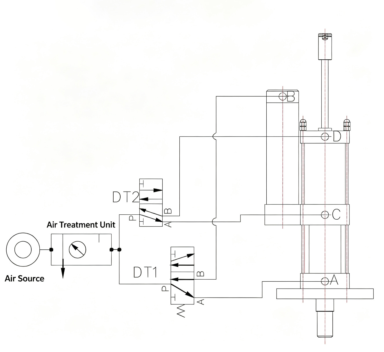
Flow: Air Source → FRL → DT1/DT2 in parallel → Ports A/B/C/D → Booster Cylinder Body. Adjustment mechanism operates on the hydraulic oil return circuit — no pneumatic modification needed.
Operation Sequence (4-Step Cycle)
JRB uses the standard two-stage 4-step cycle. The adjustable power stroke affects only Step 2 (boost depth) — the cycle sequence and valve timing remain unchanged regardless of the stroke setting.
Approach (DT1 ON)
DT1 energizes. Air pressure acts on the hydraulic oil surface in the reservoir. The cylinder section begins downward displacement — the total stroke approaches the workpiece.
Boost — Adjustable Power Stroke ⚙
Piston meets resistance. DT1 holds. DT2 energizes. The booster section engages — high-pressure force through the power stroke. The rear-port adjustment screw sets how far this stage travels (5-20 mm).
Release (DT2 OFF)
After pressure-hold duration, DT2 de-energizes. The booster section assembly resets. The cylinder releases pressure.
Return (DT1 OFF)
DT1 de-energizes. The cylinder section assembly resets. Hydraulic oil returns to the reservoir. One complete cycle finished.
Key Point: Step 2 is where JRB differs from JRA. The adjustable rear-port screw controls the hydraulic oil return volume during this step — setting the exact boost depth from 5 to 20 mm. The DT1/DT2 sequence is identical to JRA; only the mechanical stroke end-point changes.
Applications & Industries
JRB excels where production flexibility — specifically variable forming, staking, or assembly depth — is the primary selection driver. If your press station runs multiple product variants, JRB eliminates the need for multiple fixed-stroke cylinders.
Multi-Product Stamping & Forming
Different part numbers require different forming depths on the same press station. One JRB replaces multiple fixed-stroke JRA cylinders. Adjust the power stroke between batches in seconds.
Precision Riveting & Micro-Assembly
Delicate components require fine depth control to prevent over-travel damage. Calibrated adjustment at ≈1 mm/turn enables precise depth setting for electronics and micro-riveting.
Electronics & Connector Assembly
Terminal crimping, connector insertion, and PCB assembly require different depths per component type. Dial in the exact power stroke for each component family — no tooling change between types.
General Press Operations
Extrusion, bending, punching, forming, riveting, trimming/deburring, assembly, and marking/printing. The full range of standard hydro-pneumatic applications with the added benefit of adjustable depth.
JRB vs JRA vs JRC: Which Adjustable Cylinder?
Not all "adjustable" cylinders adjust the same thing. JRB adjusts the POWER stroke (forming depth). JRC adjusts the TOTAL stroke (approach distance). JRA is fixed — neither adjusts. Choosing correctly depends on what varies in your production.
| Feature | JRA | JRB | JRC |
|---|---|---|---|
| Power Stroke | Fixed | Adjustable 5–20 mm | Fixed |
| Total Stroke | Fixed | Fixed | Adjustable 50–200 mm |
| Force Range | 1–40T | 1–40T | 1–40T |
| Best When | Single product, fixed depth | Forming depth varies between products | Die height varies between tooling |
| Adjustment | — | Rear-port screw, tool-free | Tail-end mechanism |
Frequently Asked Questions
How is JRB different from JRA?
JRB adds an adjustable power stroke mechanism to the standard JRA architecture. JRA has a fixed boost depth; JRB lets you adjust it from 5 to 20 mm via a rear-port screw. Choose JRB when forming depth varies between products. If depth is fixed, JRA is simpler and more cost-effective.
What is the difference between JRB and JRC?
JRB adjusts the POWER stroke (high-pressure forming/assembly depth). JRC adjusts the TOTAL stroke (overall travel from home to end position). If your forming depth varies but the die height is constant, you need JRB. If different die heights require different total travel, you need JRC.
Does the adjustable mechanism affect reliability?
The adjustment mechanism is a simple mechanical screw on the oil-return port — no additional seals, valves, or electronics. The base cylinder is the same JRA architecture with proven field history. The adjustment screw is static during operation — it only moves during setup.
Can the adjustment be automated?
The standard adjustment is manual — a knurled screw operated by the setup technician. Automation options (motorized adjustment, position sensing) are not standard but can be discussed with JiuRong engineering for custom applications.
Installation Dimensions
JRB Adjustable Power Stroke Type 1–20T installation dimensions. Back air port distribution. All dimensions in mm. Custom configurations available on request.
| Tons | A | B | C | D | E | F | N (5B) | N (10B) | N (15B) | N (20B) |
|---|---|---|---|---|---|---|---|---|---|---|
| 1T | 160 | 100 | 132 | 228 | 14 | ZG3/8" | 40 | 60 | 60 | 80 |
| 3T | 180 | 100 | 132 | 228 | 14 | ZG3/8" | 40 | 60 | 60 | 80 |
| 5T | 190 | 118 | 155 | 275 | 17 | ZG3/8" | 40 | 60 | 60 | 80 |
| 10T | 225 | 145 | 190 | 345 | 22 | ZG3/8" | 40 | 60 | 60 | 80 |
∅63 mm — Parameter N varies with adjustable power stroke setting (5B/10B/15B/20B). Oil port at side. Back air port distribution.
| Tons | A | B | C | D | E | F | N (5B) | N (10B) | N (15B) | N (20B) |
|---|---|---|---|---|---|---|---|---|---|---|
| 3T | 180 | 100 | 132 | 228 | 14 | ZG3/8" | 40 | 60 | 60 | 80 |
| 5T | 190 | 118 | 155 | 275 | 17 | ZG3/8" | 40 | 60 | 60 | 80 |
| 10T | 225 | 145 | 190 | 345 | 22 | ZG3/8" | 40 | 60 | 60 | 80 |
| 15T | 235 | 165 | 200 | 300 | 22 | ZG1/2" | 40 | 60 | 60 | 80 |
∅80 mm — Parameter N varies with adjustable power stroke setting (5B/10B/15B/20B). Oil port at side. Back air port distribution.
| Tons | A | B | C | D | E | F | N (5B) | N (10B) | N (15B) | N (20B) |
|---|---|---|---|---|---|---|---|---|---|---|
| 5T | 190 | 118 | 155 | 275 | 17 | ZG3/8" | 40 | 60 | 60 | 80 |
| 10T | 225 | 145 | 190 | 345 | 22 | ZG1/2" | 40 | 60 | 60 | 80 |
| 15T | 235 | 165 | 200 | 310 | 22 | ZG1/2" | 40 | 60 | 60 | 80 |
| 20T | 290 | 200 | 260 | 430 | 29 | ZG3/4" | 40 | 60 | 60 | 80 |
∅100 mm — Parameter N varies with adjustable power stroke setting (5B/10B/15B/20B). Oil port at side. Back air port distribution.
| Tons | A | B | C | D | E | F | N (5B) | N (10B) | N (15B) | N (20B) |
|---|---|---|---|---|---|---|---|---|---|---|
| 10T | 225 | 145 | 190 | 345 | 22 | ZG1/2" | 60 | 80 | 80 | 100 |
| 15T | 235 | 165 | 200 | 310 | 22 | ZG1/2" | 60 | 80 | 80 | 100 |
| 20T | 290 | 200 | 260 | 460 | 31 | ZG3/4" | 60 | 80 | 80 | 100 |
| 30T | 300 | 220 | 260 | 460 | 31 | ZG3/4" | 60 | 80 | 80 | 100 |
∅125 mm — Parameter N varies with adjustable power stroke setting (5B/10B/15B/20B). Oil port at side. Back air port distribution.
| Tons | A | B | C | D | E | F | N (5B) | N (10B) | N (15B) | N (20B) |
|---|---|---|---|---|---|---|---|---|---|---|
| 15T | 290 | 200 | 260 | 460 | 31 | ZG3/4" | 80 | 100 | 100 | 120 |
| 20T | 300 | 220 | 260 | 460 | 31 | ZG3/4" | 80 | 100 | 100 | 120 |
| 30T | 360 | 260 | 320 | 565 | 38 | ZG1" | 80 | 100 | 100 | 120 |
| 40T | 390 | 290 | 380 | 620 | 43 | ZG1" | 80 | 100 | 100 | 120 |
∅160 mm — Parameter N varies with adjustable power stroke setting (5B/10B/15B/20B). Oil port at side. Back air port distribution.
Ready to Configure Your JRB?
Select your bore, tonnage, and adjustable stroke above to build your model number. Send us the code and our engineering team will reply with a quotation and dimension sheet within 24 hours.