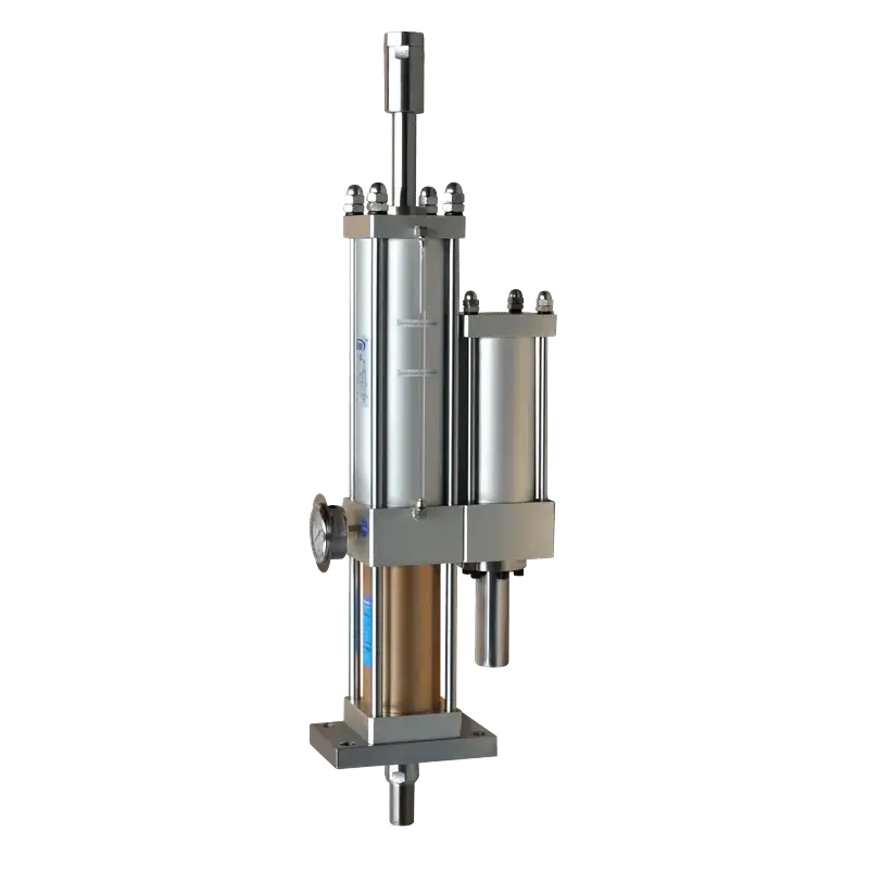
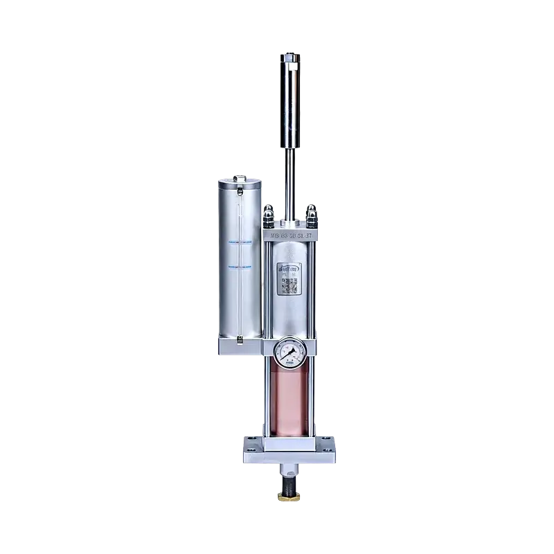
JRC Total Stroke Adjustable Hydro-Pneumatic Cylinder
A JRA-platform variant with a rear-adjustment mechanism that lets you fine-tune total stroke per die height. Same 1–40T air-driven, oil-intensified cycle, plus on-press stroke adjustability for changing tooling.
Why Total-Stroke-Adjustable?
The JRC adds a rear adjustment mechanism to the proven JRA pre-press platform. When your die height changes, dial in the total stroke at the rear nut — no shims, no disassembly, no machine re-setup.
Rear Adjustment Mechanism
Turn the rear nut to set total stroke (50–200mm range). The piston travels only what your die requires — no wasted motion, no extra cycle time.
Fast Die Changeover
Switch between tooling setups in minutes. Adjust stroke on the press without removing the cylinder or re-shimming spacers.
Fine & Accurate
Adjustment per die height is fine and accurate. Pre-press stroke tolerance ±1.00mm, power stroke tolerance ±0.20mm — consistent across the adjustable range.
Technical Specifications
Performance
| High-Pressure Output Force | 1–40 Tons |
| Operating Speed | 50–400 mm/s |
| Operating Frequency | 25–45 cycles/min |
| Total Stroke Range | 50–400 mm |
| Power Stroke Range | 5–20 mm |
| Adjustable Total Stroke | 50 / 100 / 150 / 200 mm |
| Pre-press Stroke Tolerance | +1.00 / 0.00 mm |
| Power Stroke Tolerance | +0.20 / 0.00 mm |
Pneumatic & Fluid
| Actuation Type | Double-Acting |
| Operating Pressure | 4–7 kgf/cm² (compressed air) |
| Hydraulic Medium | ISO VG68 Anti-Wear Hydraulic Oil |
| Air Cylinder Proof Pressure | 30 kgf/cm² |
| Hydraulic Cylinder Proof Pressure | 120 kgf/cm² |
| Working Temperature | 0–60 °C |
Mechanical
| Bore Sizes | ∅63, 80, 100, 125, 160 mm |
| Mounting Orientation | Vertical (normal installation) |
| Adjustment Mechanism | Rear nut, total stroke adjustable |
| Oil Port | Side drain port (ZG1/8" – ZG3/8") |
| Air Port Thread | ZG3/8" – ZG1" (bore dependent) |
| Rod End Thread | M20×1.5 – M64×2 (bore dependent) |
| Custom Options | Special customization available |
Force vs. Displacement Profile
Like the JRA, the JRC runs a two-stage cycle: fast air-driven approach, then oil-intensified boost for the final millimeters. The rear-adjustment changes where the boost starts — not the force profile itself.
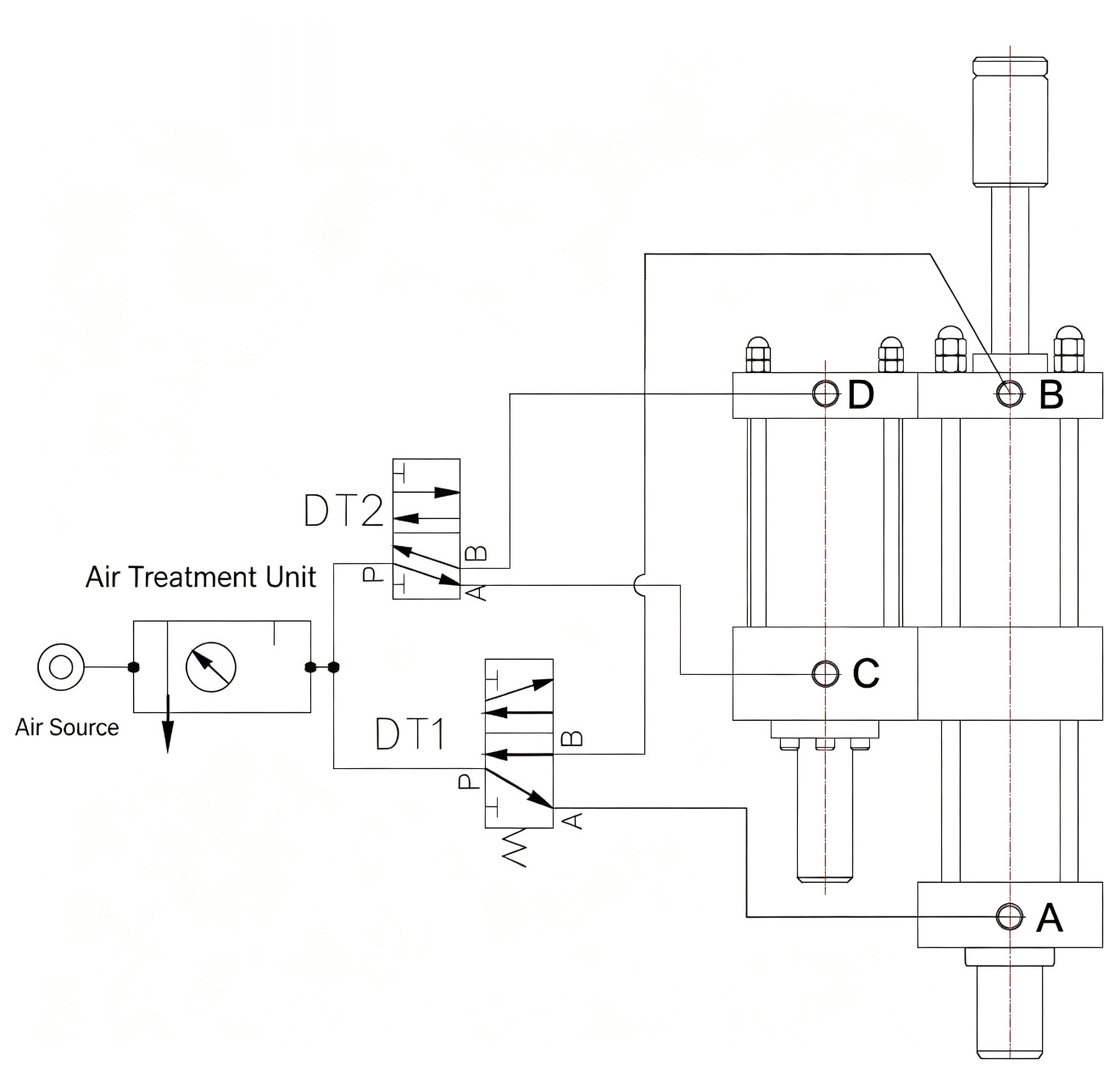
Pneumatic Circuit Diagram
The JRC uses the same two-solenoid-valve architecture as the JRA: DT1 (5-way) controls pre-press/return, DT2 (3-way) controls the boost. Air source → FRL → DT1/DT2 → cylinder body.
Action Sequence (4-Step Cycle)
The JRC runs the standard JiuRong four-step cycle. The total-stroke adjustment only changes how far step 1 travels before workpiece contact — the solenoid logic is identical.
Pre-press Approach
DT1 energized. Air pressure acts on the reservoir oil surface; the cylinder section begins its downward total stroke.
Boost Engage
Piston rod meets resistance. DT1 holds; DT2 energized. Booster section assembly begins displacement — oil intensification kicks in.
Pressure Hold / Release
Per workpiece dwell needs, DT2 de-energized. Booster section resets; the cylinder releases boost pressure.
Return
DT1 de-energized. Cylinder section resets; hydraulic oil returns to the reservoir. One cycle complete.
Mounting Configuration
The JRC is a vertical (normal) installation cylinder — rod-down on press frames and benchtop fixtures. The distinguishing feature is the rear adjustment nut at the top of the body for setting total stroke.
Vertical Mount with Rear Adjuster
Rod-down installation. The orange nut at the top is the total-stroke adjuster — turn clockwise to reduce stroke, counter-clockwise to extend. Standard for staking, riveting, and press-fit work where die height varies.
Multi-Die Flexibility
One cylinder, many die heights. The adjustable total stroke accommodates tooling changes without cylinder replacement — ideal for job shops and mixed-model production lines.
Custom Configuration
Special stroke ranges, mounting interfaces, and tonnage above 40T available as custom orders. Contact engineering with your die stack-up and force requirement for a tailored solution.
Installation Dimensions
Standard JRC dimensions by bore and tonnage. Total length N depends on power stroke (5/10/15/20mm) — the table shows N at 10mm power stroke; see notes for other values. Full CAD (DWG/STEP) available on request.
| Model | Force | N (10mm p-stroke) | A | B | C | D | E | F | H | I | J | K | Rod M | Air G | Oil O | Q |
|---|---|---|---|---|---|---|---|---|---|---|---|---|---|---|---|---|
| JRC-63-100-10L-1T-100A | 1T | 380 | 160 | 100 | 132 | 65 | 19 | 13 | 117 | 50 | 75 | 35 | M20×1.5 | ZG3/8" | ZG1/8" | 9 |
| JRC-63-100-10L-3T-100A | 3T | 425 | 180 | 100 | 132 | 65 | 19 | 13 | 117 | 50 | 75 | 35 | M20×1.5 | ZG3/8" | ZG1/8" | 9 |
| JRC-63-100-10L-5T-100A | 5T | 484 | 190 | 118 | 155 | 65 | 22 | 17 | 125 | 50 | 90 | 40 | M24×2 | ZG3/8" | ZG1/8" | 12 |
| JRC-63-100-10L-10T-100A | 10T | 580 | 225 | 145 | 190 | 85 | 28 | 24 | 135 | 85 | 110 | 45 | M30×2 | ZG1/2" | ZG1/8" | 14 |
| Model | Force | N (10mm p-stroke) | A | B | C | D | E | F | H | I | J | K | Rod M | Air G | Oil O | Q |
|---|---|---|---|---|---|---|---|---|---|---|---|---|---|---|---|---|
| JRC-80-100-10L-3T-100A | 3T | 425 | 180 | 100 | 132 | 65 | 22 | 17 | 125 | 50 | 90 | 40 | M24×2 | ZG3/8" | ZG1/8" | 9 |
| JRC-80-100-10L-5T-100A | 5T | 484 | 190 | 118 | 155 | 65 | 22 | 17 | 125 | 85 | 110 | 45 | M30×2 | ZG3/8" | ZG1/8" | 12 |
| JRC-80-100-10L-10T-100A | 10T | 580 | 225 | 145 | 190 | 85 | 28 | 24 | 135 | 110 | 120 | 60 | M36×2 | ZG1/2" | ZG1/8" | 14 |
| JRC-80-100-10L-15T-100A | 15T | 633 | 235 | 165 | 200 | 100 | 32 | 28 | 150 | 130 | 130 | 60 | M42×2 | ZG1/2" | ZG1/8" | 18 |
| Model | Force | N (10mm p-stroke) | A | B | C | D | E | F | H | I | J | K | Rod M | Air G | Oil O | Q |
|---|---|---|---|---|---|---|---|---|---|---|---|---|---|---|---|---|
| JRC-100-100-10L-5T-100A | 5T | 484 | 190 | 118 | 155 | 65 | 22 | 17 | 125 | 85 | 110 | 45 | M30×2 | ZG3/8" | ZG1/4" | 12 |
| JRC-100-100-10L-10T-100A | 10T | 580 | 225 | 145 | 190 | 85 | 28 | 24 | 135 | 110 | 120 | 60 | M36×2 | ZG1/2" | ZG1/4" | 14 |
| JRC-100-100-10L-15T-100A | 15T | 633 | 235 | 165 | 200 | 100 | 32 | 28 | 150 | 130 | 130 | 60 | M42×2 | ZG1/2" | ZG1/4" | 18 |
| JRC-100-100-10L-20T-100A | 20T | 750 | 290 | 200 | 260 | 120 | 38 | 34 | 170 | 160 | 160 | 70 | M48×2 | ZG3/4" | ZG1/4" | 20 |
| Model | Force | N (10mm p-stroke) | A | B | C | D | E | F | H | I | J | K | Rod M | Air G | Oil O | Q |
|---|---|---|---|---|---|---|---|---|---|---|---|---|---|---|---|---|
| JRC-125-100-10L-10T-100A | 10T | 580 | 225 | 145 | 190 | 85 | 28 | 24 | 135 | 110 | 120 | 60 | M36×2 | ZG1/2" | ZG1/4" | 14 |
| JRC-125-100-10L-15T-100A | 15T | 633 | 235 | 165 | 200 | 100 | 32 | 28 | 150 | 130 | 130 | 60 | M42×2 | ZG1/2" | ZG1/4" | 18 |
| JRC-125-100-10L-20T-100A | 20T | 750 | 290 | 200 | 260 | 120 | 38 | 34 | 170 | 160 | 160 | 70 | M48×2 | ZG3/4" | ZG1/4" | 20 |
| JRC-125-100-10L-30T-100A | 30T | 840 | 300 | 220 | 280 | 140 | 42 | 38 | 190 | 180 | 190 | 80 | M56×2 | ZG3/4" | ZG1/4" | 24 |
| Model | Force | N (10mm p-stroke) | A | B | C | D | E | F | H | I | J | K | Rod M | Air G | Oil O | Q |
|---|---|---|---|---|---|---|---|---|---|---|---|---|---|---|---|---|
| JRC-160-100-10L-15T-100A | 15T | 633 | 290 | 200 | 260 | 120 | 32 | 28 | 150 | 130 | 160 | 60 | M42×2 | ZG1/2" | ZG3/8" | 18 |
| JRC-160-100-10L-20T-100A | 20T | 750 | 300 | 220 | 280 | 140 | 38 | 34 | 170 | 160 | 190 | 70 | M48×2 | ZG3/4" | ZG3/8" | 20 |
| JRC-160-100-10L-30T-100A | 30T | 840 | 360 | 260 | 340 | 160 | 42 | 38 | 190 | 180 | 230 | 80 | M56×2 | ZG3/4" | ZG3/8" | 24 |
| JRC-160-100-10L-40T-100A | 40T | 990 | 390 | 290 | 380 | 180 | 50 | 45 | 210 | 210 | 270 | 95 | M64×2 | ZG1" | ZG3/8" | 28 |
All dimensions in mm. N = total length at 10mm power stroke. For 5mm power stroke subtract ~5–15mm; for 15mm add ~145–200mm; for 20mm add ~270–340mm (varies by bore/tonnage). L = N + S (total stroke). P = mounting hole count is 8 for ∅63, 11 for ∅80/100, 14 for ∅125/160. S = total stroke (adjustable 50–200mm via rear nut). Custom configurations above 40T available on request.
JRC vs JRA: Fixed Stroke or Adjustable?
Both share the same pre-press boosting mechanism, force range, and bore sizes. The JRC adds a rear-adjustment nut so total stroke can be tuned to die height — ideal for mixed-tooling presses.
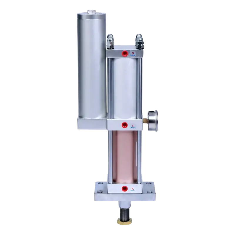
JRA
Fixed-Stroke StandardRod-down standard pre-press cylinder with fixed total stroke. The workhorse for dedicated single-tooling presses where die height is constant.
| Total Stroke | Fixed at order (10–300 mm) |
| Force Range | 1–40 T |
| Bore Sizes | ∅63 / 80 / 100 / 125 / 160 |
| Power Stroke | 5–50 mm |
| Mounting | Vertical (rod-down) |
- Dedicated single-tooling presses
- High-volume dedicated lines
- Constant die-height applications
- Lower-cost standard installations
JRC
Total Stroke AdjustableSame pre-press mechanism, plus a rear nut that adjusts total stroke (50–200mm range) per die height. Built for job shops and mixed-model lines.
| Total Stroke | Adjustable 50–200 mm (rear nut) |
| Force Range | 1–40 T |
| Bore Sizes | ∅63 / 80 / 100 / 125 / 160 |
| Power Stroke | 5–20 mm |
| Mounting | Vertical (rod-down) |
- Mixed-tooling / job-shop presses
- Frequent die changeovers
- Prototype & short-run work
- Varying workpiece heights
Internal mechanism, force output, and pneumatic circuit are identical — only the rear adjustment mechanism and total-stroke range differ. Unsure which to choose? Contact our engineering team.
Build Your Model Number
Configure your JRC and see the model code update in real time. The JRC code adds a final "A" segment for the adjustable total stroke range — e.g. JRC-80-100-10L-5T-100A.
Values are theoretical. Actual output is recommended not to exceed 50% of theoretical to preserve operating speed. For critical applications, apply a 1.5× safety factor.
Typical Applications
The JRC shines where workpiece heights vary or tooling changes frequently — extrusion, bending, punching, forming, riveting, trimming, assembly, and marking operations.
Resources & Downloads
JRC Product Catalog (PDF)
Complete specifications, all bore/tonnage combinations, ordering guide
Operation & Maintenance Manual
Installation, rear-nut adjustment procedure, maintenance intervals
CAD Drawings (DWG / STEP)
2D/3D models for your specific bore, tonnage, and adjustable range
Ready to Configure Your JRC?
Send us your required tonnage, total stroke, power stroke, and adjustable range. Our engineering team will reply with a quotation and dimension sheet within 24 hours.