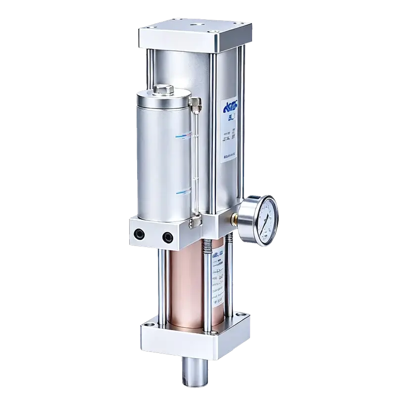
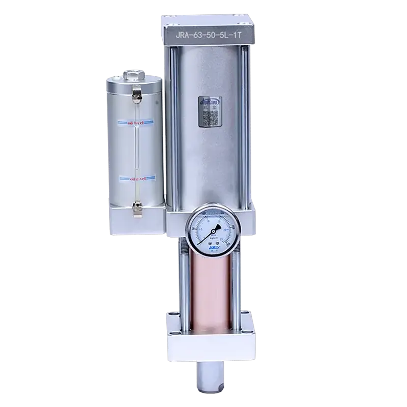
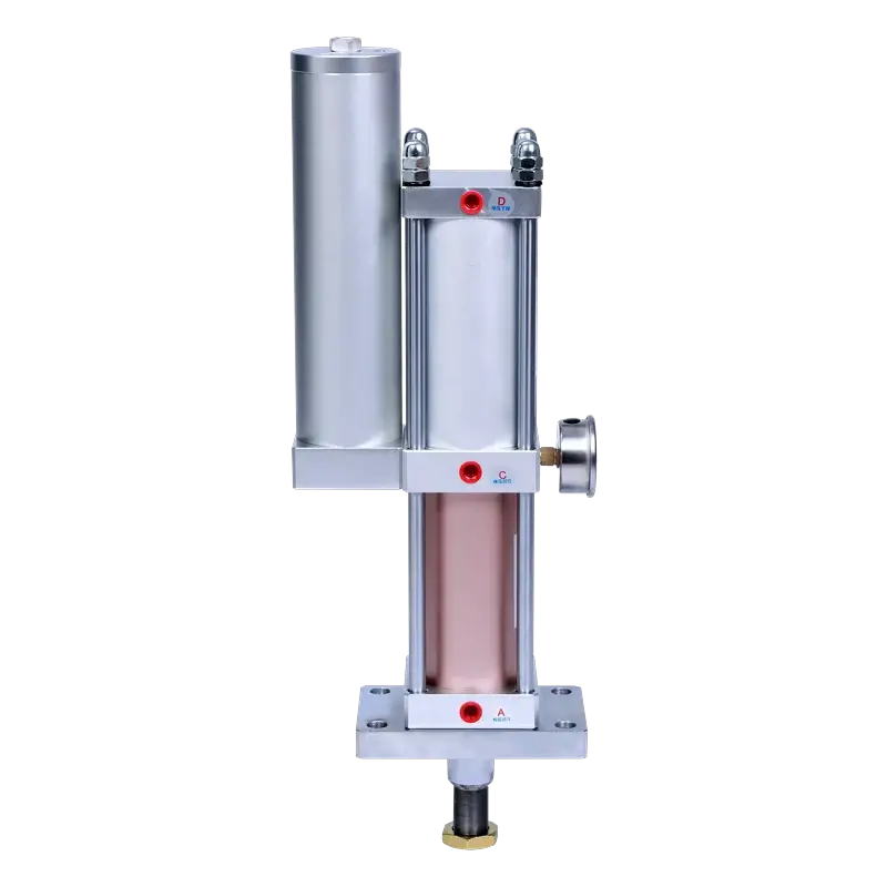
JRE Direct-Acting Hydro-Pneumatic Cylinder
Full-stroke high pressure in a compact form. The JRE operates like an air cylinder but delivers oil-intensified force from the very first millimeter — no pre-press phase, no separate boost stage. Ideal for short-stroke, high-force tasks: marking, bearing assembly, riveting, and sheet metal forming.
Why Direct-Acting?
Unlike pre-press types (JRA/JRAA) that use a two-stage cycle — fast air approach followed by oil-intensified boost — the JRE applies high pressure throughout the entire stroke. Total stroke equals power stroke. The result: cylinder-like simplicity with far greater force.
Low-force air approach → high-force oil boost at the end. Two solenoid valves, 4-step cycle.
High force from start to finish. One solenoid valve, 3-step cycle. Short stroke, big output.
Full-Stroke High Pressure
Operates like an air cylinder but with oil-intensified force throughout the entire stroke — no low-force approach phase.
Larger Output Than Air Cylinders
Delivers significantly more force than a same-bore air cylinder, with smooth and fast operating speed.
Simple 3-Step Cycle
Single solenoid valve (DT1) simultaneously controls air and oil cylinders. Return → boost → return — cycle complete.
Short Stroke, High Force
Designed for applications needing high force over a short distance: marking, bearing assembly, riveting, forming.
Vertical or Horizontal Mount
Standard vertical mounting (A). Horizontal mounting (B) available with customizable front neck for side-press applications.
5 Bore Sizes, 3 Tonnages
∅50–125mm bores with 5T, 10T, and 13T output options at 4–7 kgf/cm² air supply. Custom configurations available.
Technical Specifications
Performance
| Actuation Type | Double-acting |
| High Pressure Output | 1–13 tons |
| Operating Speed | 50–400 mm/s |
| Operating Frequency | 25–45 cycles/min |
| Power Stroke Tolerance | +0.20 / 0.00 mm |
| Pre-press Stroke Tolerance | +1.00 / 0.00 mm |
Fluid
| Operating Pressure | 4–7 kgf/cm² (compressed air) |
| Hydraulic Medium | ISO VG68 anti-wear hydraulic oil |
| Air Cylinder Proof Pressure | 30 kgf/cm² |
| Oil Cylinder Proof Pressure | 120 kgf/cm² |
| Working Temperature | 0–60 °C |
Mechanical
| Bore Sizes | ∅50, 63, 80, 100, 125 mm |
| Power Stroke Options | 5, 10, 15, 20, 25 mm |
| Output Tonnages | 5T, 10T, 13T |
| Mounting Type | A – Vertical (standard), B – Horizontal |
| Design Feature | Full-stroke high pressure, short stroke high force |
| Custom Options | Special strokes, horizontal front neck, non-standard bores |
Force vs. Displacement Profile
The JRE delivers high force across the entire stroke — there is no low-force approach phase. From the moment the piston begins moving to the end of stroke, oil-intensified pressure is fully engaged. This makes the JRE ideal for short-stroke applications where force must be present immediately.
Key difference from JRA: The JRA starts with a low-force air approach and only triggers oil boost at workpiece contact. The JRE engages full oil-intensified force from the very beginning — total stroke equals power stroke.
Pneumatic Circuit Diagram
The JRE uses a single solenoid valve (DT1) to simultaneously control the air cylinder and oil cylinder. Air flows through the treatment unit and solenoid valve, driving the air piston which directly actuates the oil piston for high-pressure output.
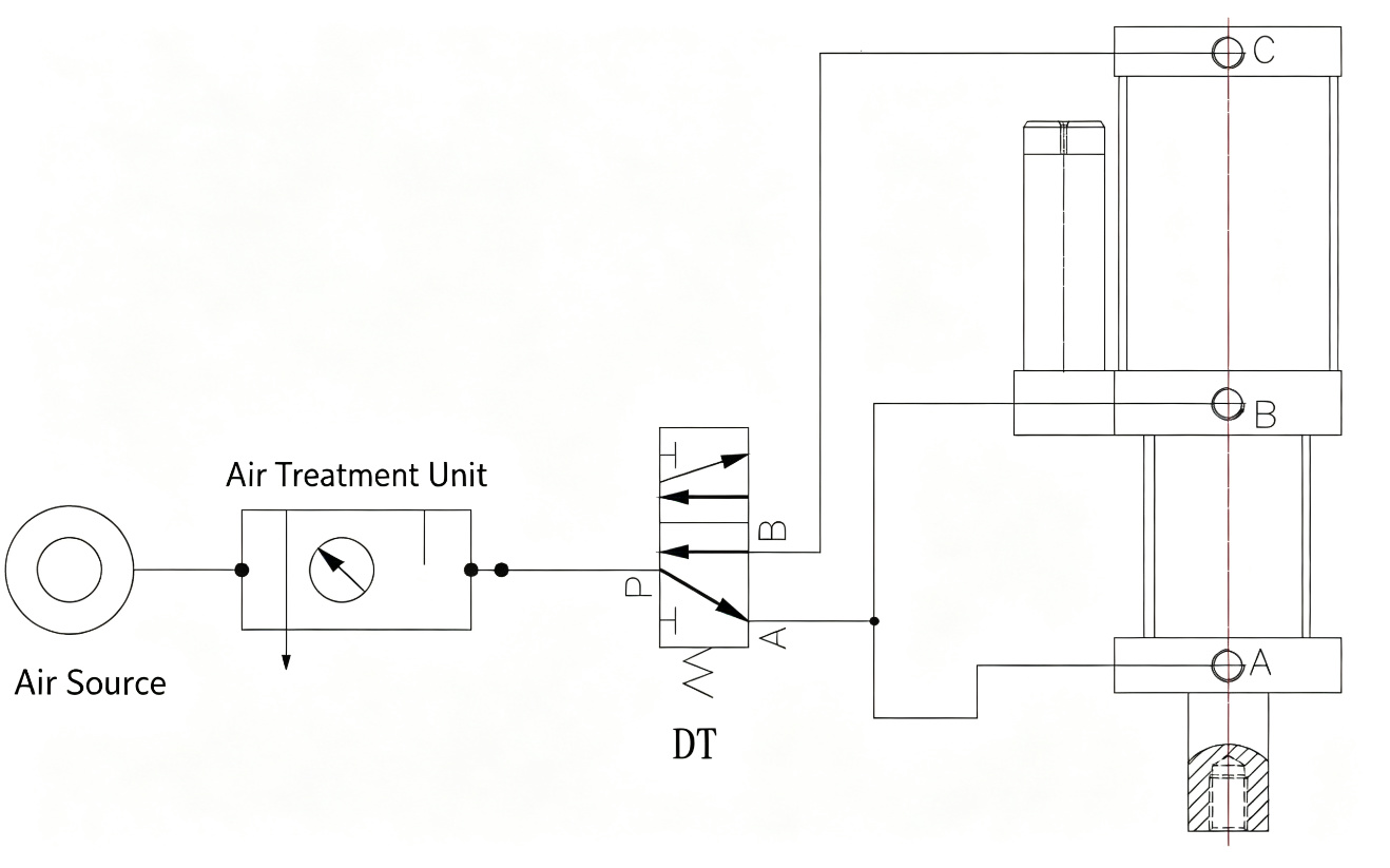
Flow: Air Source → Air Treatment Unit (FRL) → Port P → Solenoid Valve DT1 → Ports A/B alternate → Air piston moves → Oil piston boosts → High-pressure output
Operation Sequence (3-Step Cycle)
The JRE uses a simplified 3-step cycle — no independent boost stage control. DT1 simultaneously controls both the air cylinder and oil cylinder. This is simpler than the 4-step JRA cycle.
Return / Home Position
After connecting the pneumatic circuit per the diagram above, open the air source. The booster cylinder is in the return (home) position — DT1 is de-energized.
Direct Boost (Power Stroke)
DT1 energizes, switching the air circuit. Air pressure acts on the air cylinder piston, causing displacement. The oil cylinder simultaneously begins boosting — high force is applied from the start.
Return & Reset
After holding pressure as needed, DT1 de-energizes. The air circuit switches again, returning both the air cylinder and oil cylinder to their initial state simultaneously. One action cycle is complete.
Note: JRE is direct-acting type — the action cycle has 3 steps with no independent booster stage control. DT1 simultaneously controls the air cylinder and oil cylinder. Pressure-hold time is adjustable based on workpiece requirements.
Mounting Configurations
The JRE supports vertical (standard) and horizontal mounting. Horizontal mounting features a customizable front neck for side-press applications. Other mounting orientations can be specified before ordering.
Vertical Mount (Type A)
Rod-down installation on press frames, C-frames, and benchtop fixtures. The standard configuration for marking, riveting, and press-fit operations.
Horizontal Mount (Type B)
Rod-forward horizontal installation with customizable front neck. For inline pressing, slide mechanisms, and side-press fixtures where vertical space is limited.
Custom Mount
Rod-up, angled, or other special mounting orientations. Available as custom order with modified port and body configuration. Contact engineering for application review.
Installation Dimensions
Standard JRE 1–13T installation dimensions by bore size. Total length (R) varies with power stroke selection. All dimensions in mm. Custom configurations available on request.
∅50 mm Bore — Base Dimensions
| Tonnage | A | B | C | D | E | H | I | J | K | N | O | P | Q | M (Rod Thread) | F (Air Port) | G (Back Port) |
|---|---|---|---|---|---|---|---|---|---|---|---|---|---|---|---|---|
| 5T | 95 | 70 | 70 | 18 | 16 | 96 | 30 | 65 | 28 | 152 | 18 | 8 | 100 | M16 | ZG3/8" | ZG3/8" |
| 10T | 95 | 70 | 76 | 18 | 16 | 96 | 30 | 65 | 28 | 152 | 18 | 8 | 100 | M16 | ZG3/8" | ZG3/8" |
| 13T | 110 | 90 | 90 | 20 | 18 | 108 | 35 | 80 | 30 | 182 | 22 | 10 | 120 | M20 | ZG3/8" | ZG3/8" |
Total Length (R) by Power Stroke
| Tonnage | R @ 5mm stroke | R @ 10mm stroke | R @ 15mm stroke | R @ 20mm stroke | R @ 25mm stroke |
|---|---|---|---|---|---|
| 5T | 130 | 165 | 200 | 235 | 265 |
| 10T | 130 | 165 | 200 | 235 | 265 |
| 13T | 150 | 215 | 270 | 325 | 380 |
∅63 mm Bore — Base Dimensions
| Tonnage | A | B | C | D | E | H | I | J | K | N | O | P | Q | M (Rod Thread) | F (Air Port) | G (Back Port) |
|---|---|---|---|---|---|---|---|---|---|---|---|---|---|---|---|---|
| 5T | 110 | 90 | 90 | 20 | 18 | 110 | 35 | 80 | 30 | 182 | 22 | 10 | 120 | M20 | ZG3/8" | ZG3/8" |
| 10T | 110 | 90 | 90 | 20 | 18 | 110 | 35 | 80 | 30 | 182 | 22 | 10 | 120 | M20 | ZG3/8" | ZG3/8" |
| 13T | 140 | 110 | 140 | 25 | 22 | 130 | 40 | 105 | 35 | 210 | 25 | 12 | 140 | M24 | ZG1/2" | ZG1/2" |
Total Length (R) by Power Stroke
| Tonnage | R @ 5mm stroke | R @ 10mm stroke | R @ 15mm stroke | R @ 20mm stroke | R @ 25mm stroke |
|---|---|---|---|---|---|
| 5T | 170 | 215 | 260 | 305 | 350 |
| 10T | 170 | 215 | 260 | 305 | 350 |
| 13T | 217 | 272 | 338 | 395 | 445 |
∅80 mm Bore — Base Dimensions
| Tonnage | A | B | C | D | E | H | I | J | K | N | O | P | Q | M (Rod Thread) | F (Air Port) | G (Back Port) |
|---|---|---|---|---|---|---|---|---|---|---|---|---|---|---|---|---|
| 5T | 140 | 110 | 140 | 25 | 22 | 130 | 40 | 105 | 35 | 210 | 25 | 12 | 140 | M24 | ZG3/8" | ZG1/2" |
| 10T | 140 | 110 | 140 | 25 | 22 | 130 | 40 | 105 | 35 | 210 | 25 | 12 | 140 | M24 | ZG1/2" | ZG1/2" |
| 13T | 180 | 146 | 180 | 30 | 26 | 160 | 50 | 130 | 50 | 265 | 30 | 14 | 180 | M30 | ZG1/2" | ZG3/4" |
Total Length (R) by Power Stroke
| Tonnage | R @ 5mm stroke | R @ 10mm stroke | R @ 15mm stroke | R @ 20mm stroke | R @ 25mm stroke |
|---|---|---|---|---|---|
| 5T | 217 | 272 | 338 | 395 | 445 |
| 10T | 217 | 272 | 338 | 395 | 445 |
| 13T | 266 | 336 | 420 | 490 | 560 |
∅100 mm Bore — Base Dimensions
| Tonnage | A | B | C | D | E | H | I | J | K | N | O | P | Q | M (Rod Thread) | F (Air Port) | G (Back Port) |
|---|---|---|---|---|---|---|---|---|---|---|---|---|---|---|---|---|
| 5T | 180 | 146 | 180 | 30 | 26 | 160 | 50 | 130 | 50 | 265 | 30 | 14 | 180 | M30 | ZG1/2" | ZG3/4" |
| 10T | 180 | 146 | 180 | 30 | 26 | 160 | 50 | 130 | 50 | 265 | 30 | 14 | 180 | M30 | ZG1/2" | ZG3/4" |
| 13T | 200 | 160 | 200 | 35 | 30 | 190 | 60 | 155 | 60 | 320 | 35 | 16 | 200 | M36 | ZG3/4" | ZG1" |
Total Length (R) by Power Stroke
| Tonnage | R @ 5mm stroke | R @ 10mm stroke | R @ 15mm stroke | R @ 20mm stroke | R @ 25mm stroke |
|---|---|---|---|---|---|
| 5T | 266 | 336 | 420 | 490 | 560 |
| 10T | 266 | 336 | 420 | 490 | 560 |
| 13T | 330 | 410 | 510 | 595 | 680 |
∅125 mm Bore — Base Dimensions
| Tonnage | A | B | C | D | E | H | I | J | K | N | O | P | Q | M (Rod Thread) | F (Air Port) | G (Back Port) |
|---|---|---|---|---|---|---|---|---|---|---|---|---|---|---|---|---|
| 5T | 200 | 160 | 200 | 35 | 30 | 190 | 60 | 155 | 60 | 320 | 35 | 16 | 200 | M36 | ZG3/4" | ZG1" |
| 10T | 200 | 160 | 200 | 35 | 30 | 190 | 60 | 155 | 60 | 320 | 35 | 16 | 200 | M36 | ZG3/4" | ZG1" |
| 13T | 250 | 200 | 250 | 40 | 36 | 230 | 75 | 195 | 75 | 395 | 40 | 20 | 250 | M48 | ZG1" | ZG1 1/4" |
Total Length (R) by Power Stroke
| Tonnage | R @ 5mm stroke | R @ 10mm stroke | R @ 15mm stroke | R @ 20mm stroke | R @ 25mm stroke |
|---|---|---|---|---|---|
| 5T | 330 | 410 | 510 | 595 | 680 |
| 10T | 330 | 410 | 510 | 595 | 680 |
| 13T | 410 | 510 | 630 | 735 | 840 |
All dimensions in mm. S = total stroke (power stroke). R values represent total cylinder length at the indicated power stroke. For custom configurations or non-standard strokes, contact engineering for detailed dimension sheets.
Theoretical Output Force
Output force varies with air supply pressure. Below are theoretical values for each bore and tonnage combination across 4–7 kgf/cm².
| Bore | Tonnage | 4 kgf/cm² | 5 kgf/cm² | 6 kgf/cm² | 7 kgf/cm² |
|---|---|---|---|---|---|
| 50mm | 5T | 4,000 | 5,000 | 6,000 | 7,000 |
| 50mm | 10T | 8,000 | 10,000 | 12,000 | 14,000 |
| 50mm | 13T | 10,400 | 13,000 | 15,600 | 18,200 |
| 63mm | 5T | 4,050 | 5,060 | 6,075 | 7,087 |
| 63mm | 10T | 8,100 | 10,125 | 12,150 | 14,175 |
| 63mm | 13T | 10,530 | 13,163 | 15,795 | 18,428 |
| 80mm | 5T | 4,200 | 5,250 | 6,300 | 7,350 |
| 80mm | 10T | 8,400 | 10,500 | 12,600 | 14,700 |
| 80mm | 13T | 10,920 | 13,650 | 16,380 | 19,110 |
| 100mm | 5T | 4,500 | 5,625 | 6,750 | 7,875 |
| 100mm | 10T | 9,000 | 11,250 | 13,500 | 15,750 |
| 100mm | 13T | 11,700 | 14,625 | 17,550 | 20,475 |
| 125mm | 5T | 5,000 | 6,250 | 7,500 | 8,750 |
| 125mm | 10T | 10,000 | 12,500 | 15,000 | 17,500 |
| 125mm | 13T | 13,000 | 16,250 | 19,500 | 22,750 |
Note: Values are theoretical. Actual output force is recommended not to exceed 50% of the above data to avoid affecting operating speed. Unit: kgf. Reference pressure for output calculation: 6 kgf/cm².
JRE vs JREB vs JRA: Which Cylinder?
JRE and JREB share the same direct-acting mechanism — only mounting direction differs. JRA adds a two-stage pre-press approach for longer strokes and higher tonnage. Compare all three to find the right fit for your application.
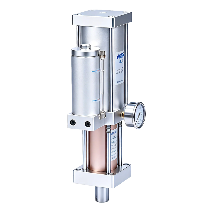
JRE
Vertical Direct-ActingRod pushes downward. Mounts on top of a fixture or press plate. The standard configuration for top-down work.
| Mounting | Vertical (rod-down) |
| Force Range | 1–13 T |
| Bore Sizes | ∅50 / 63 / 80 / 100 / 125 |
| Power Stroke | 5–25 mm |
| Solenoid Valves | 1 × 5/2-way |
| Cycle Rate | 25–45 cycles/min |
- Vertical marking & stamping
- Top-down press-fit assembly
- Riveting from above
- Benchtop C-frame presses
JREB
Horizontal Direct-ActingRod pushes horizontally. Dedicated horizontal body with foot mounting. For side-load applications where vertical mounting is impractical.
| Mounting | Horizontal (rod-forward) |
| Force Range | 1–13 T |
| Bore Sizes | ∅50 / 63 / 80 / 100 / 125 |
| Power Stroke | 5–25 mm |
| Solenoid Valves | 1 × 5/2-way |
| Cycle Rate | 25–45 cycles/min |
- Horizontal extrusion & bending
- Inline assembly line stations
- Side-press & horizontal forming
- Fixtures where rod must push sideways
JRA
Pre-press · VerticalTwo-stage pre-press design — fast low-force approach followed by high-force boost. Vertical rod-down. For longer strokes and higher tonnage.
| Mounting | Vertical (rod-down) |
| Force Range | 1–40 T |
| Bore Sizes | ∅63 / 80 / 100 / 125 / 160 |
| Power Stroke | 5–50 mm (boost) |
| Solenoid Valves | 2 × 5/2 + 3/2-way |
| Cycle Rate | 25–45 cycles/min |
- General press work with long approach
- Two-stage operation (approach + boost)
- Higher tonnage applications
- Longer strokes (10–300 mm total)
JRE and JREB share the same direct-acting internals — only mounting differs. JRA uses a two-stage pre-press design for longer strokes and higher tonnage. Need a custom configuration? Contact our engineering team.
Build Your Model Number
The JRE model code: JR-E-bore-power stroke-tonnage-mounting type. Configure below to see your model code update in real time.
Values are theoretical. Actual output may vary with seal friction, line losses, and hydraulic oil condition. For critical applications, apply a 1.5× safety factor.
Selection Guide
When selecting a JRE model, consider these six key parameters. Our engineering team will help match the right configuration to your application.
Total Bore
Required booster cylinder bore diameter (mm) based on force and speed requirements.
Power Stroke
Required pressure stroke (mm). For JRE, total stroke equals power stroke — choose 5–25mm.
Output Tonnage
Required output force (tons) after boosting at the reference 6 kgf/cm² air pressure.
Operating Frequency
Required cycle frequency (cycles/min). JRE supports 25–45 cycles/min, inversely proportional to stroke length.
Return Force
Required return / lifting force (kgf) to retract the piston and tooling weight.
Mounting Type
Installation orientation: A (vertical, standard) or B (horizontal with customizable front neck).
Typical Applications
The JRE excels in short-stroke, high-force tasks where force must be present from the first millimeter. Ideal for marking, bearing assembly, electronic component riveting, and sheet metal forming.
Ready to Configure Your JRE?
Send us your required tonnage, power stroke, and mounting type. Our engineering team will reply with a quotation and dimension sheet within 24 hours.