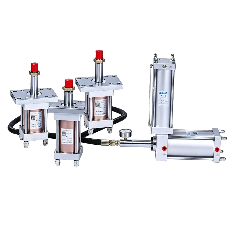
JRH Pre-Press Separated Hydro-Pneumatic Booster
Two-stage pre-press booster with separated hydraulic cylinders. The booster body mounts horizontally while JRYG cylinders install at any angle — supporting one-to-multiple configurations for distributed press-fitting and clamping.
Why Choose a Separated Booster?
When the actuator must live where the booster cannot, a separated architecture delivers both high force and layout freedom.
Integrated Cylinder
JRA / JRE — all-in-one units where the air cylinder, oil chamber, and output rod share one body. Compact and simple, but the entire unit must mount at the work point in a fixed orientation.
JRH Separated Booster
The booster body stays remote — horizontally mounted on the machine frame — while compact JRYG hydraulic cylinders deliver force exactly where needed, at any angle, even in groups.
Two-Stage Pre-Press Action
Fast low-force approach followed by high-pressure boost — controlled by DT1 (pre-press) and DT2 (power stroke) for staged, energy-efficient operation.
Separated Installation
Booster body mounts horizontally; JRYG oil cylinders install at any angle. Ideal when the work point is too small, hot, or awkward for an integrated cylinder.
One-to-Multiple Output
A single JRH booster can drive 1, 2, 3, or more JRYG cylinders simultaneously — perfect for distributed clamping, multi-point press-fitting, and brake/clutch systems.
7 Boost Ratios Available
From 7.7:1 to 41.1:1 — match the ratio to your required output force and oil volume without oversizing the air cylinder.
Clean, Oil-Mist-Free
Hydraulic oil stays sealed in the closed circuit. No oil mist exhaust — suitable for clean-rooms, electronics assembly, and food-adjacent automation.
Built to Order
Non-standard boost ratios, oil volumes, cylinder strokes, and mounting configurations available. Every unit is ISO 9001:2015 certified and backed by a 2-year warranty.
Technical Specifications
Performance
| Actuation Type | Single-acting (booster body) |
| Boost Ratio Range | 7.7:1 – 41.1:1 |
| Oil Displacement | 70 – 2535 cc |
| Operating Speed | 50 – 450 mm/s |
| Cycle Rate | 25 – 45 cycles/min |
Fluid & Control
| Working Medium | Compressed air (40 µm filtered) |
| Operating Pressure | 4 – 7 kgf/cm² |
| Control Valves | 2 × two-position 5-way solenoid (DT1 + DT2) |
| Air Cylinder Proof Pressure | 30 kgf/cm² |
| Lubrication | Oil-mist-free (closed oil circuit) |
System Configuration
| Booster Bore Options | Ø63 / 80 / 100 / 125 / 160 / 180 mm |
| Matched Cylinder Bore | Ø63 / 80 / 100 / 125 mm (std.) |
| Matched Cylinder Stroke | 5 – 30 mm (std.), custom to 400 mm |
| Booster Mounting | Horizontal |
| Cylinder Mounting | Any angle (flange mount) |
Boost Ratio & Oil Displacement
Oil displacement (cc) is determined by the combination of air cylinder bore and boost ratio. Find your required oil volume, then read off the corresponding ratio and bore.
| Bore \ Ratio | L07 7.7:1 | L16 16.6:1 | L20 20:1 | L25 25.4:1 | L28 28.4:1 | L36 36.4:1 | L41 41.1:1 |
|---|---|---|---|---|---|---|---|
| Ø80 mm | 70 cc | 120 cc | 200 cc | 350 cc | 430 cc | 584 cc | 738 cc |
| Ø100 mm | 85 cc | 146 cc | 242 cc | 423 cc | 520 cc | 692 cc | 880 cc |
| Ø125 mm | 120 cc | 206 cc | 340 cc | 595 cc | 732 cc | 972 cc | 1234 cc |
| Ø160 mm | 215 cc | 369 cc | 610 cc | 1068 cc | 1314 cc | 1740 cc | 2210 cc |
| Ø180 mm | 217 cc | 423 cc | 699 cc | 1225 cc | 1507 cc | 1995 cc | 2535 cc |
Values are reference oil displacement at full stroke. Actual high-pressure output per cycle depends on matched cylinder bore and power-stroke setting. Confirm with our engineering team for critical applications.
Pneumatic-Hydraulic Circuit
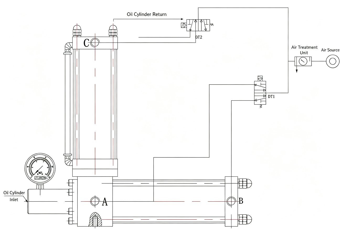
Circuit Components
- SRCCompressed Air Source
Plant air supply, 4–7 kgf/cm²
- FRLAir Treatment Unit
Filter · Regulator · Lubricator
- DT1Solenoid Valve DT1
Controls pre-press section — drives fast approach stroke
- DT2Solenoid Valve DT2
Controls booster section — engages high-pressure stroke
- COil Reservoir Port
Air-to-oil conversion chamber (top of vertical reservoir)
- ACylinder Port A
Hydraulic oil inlet to JRYG cylinder
- BCylinder Port B
Hydraulic oil return from JRYG cylinder
- PGHydraulic Pressure Gauge
Monitors boosted oil pressure at the cylinder
4-Step Operation Sequence
JRH uses a pre-press two-valve sequence: DT1 handles the fast approach, DT2 engages the high-pressure boost, then both reset in order.
Pre-Press Approach
DT1 energizes. Air pressure acts on the oil surface in the reservoir, pushing hydraulic oil through port A to the JRYG cylinder. The piston advances rapidly at low force until it contacts the workpiece.
High-Pressure Boost
Resistance builds — DT1 holds while DT2 energizes. The booster air cylinder drives the intensifier piston, multiplying hydraulic pressure by the selected boost ratio. The JRYG cylinder outputs full force.
Pressure Release
After the required dwell/hold time, DT2 de-energizes. The booster section retracts, hydraulic pressure drops, and the system releases force on the workpiece while DT1 maintains position.
Return & Reset
DT1 de-energizes. The air cylinder retracts, oil flows back through port B to the reservoir, and the JRYG piston returns to home. One complete cycle is finished and the system is ready for the next.
System Configuration Options
The JRH system separates the power source from the actuator, giving you three dimensions of layout freedom.
Horizontal Booster Body
The JRH booster body mounts horizontally on the machine frame — away from heat, coolant, or space constraints at the work point. Standard foot or flange mounting.
Any-Angle Oil Cylinders
JRYG matched cylinders are flange-mounted and can be installed vertically, horizontally, upside-down, or at any custom angle. The oil circuit is fully sealed — orientation does not affect performance.
One-to-Multiple Output
Drive 1, 2, 3, or more JRYG cylinders from a single booster. All cylinders act in parallel — ideal for multi-point clamping, distributed press-fitting, and brake/clutch circuits with synchronized force.
Booster Body Dimensions
Fixed dimensions (A–F) depend on bore only. Variable dimensions (G–J) and oil displacement change with the selected boost ratio. Switch between bore sizes below.
Fixed Dimensions (mm)
| Parameter | Description | Value |
|---|---|---|
| A | Total width | 80 |
| B | Dimension B | 95 |
| C | Dimension C | 70 |
| D | Dimension D | 165 |
| E | Thread specification | M10 |
| F | Air port thread | ZG3/8" |
Dimensions by Boost Ratio (mm) & Oil Displacement (cc)
| Ratio Code | Boost Ratio | G | H | I | J | Oil Disp. |
|---|---|---|---|---|---|---|
| L07 | 7.7:1 | 233.8 | 405 | 596 | 738 | 70 cc |
| L16 | 16.6:1 | 295 | 498 | 738 | 912 | 120 cc |
| L20 | 20:1 | 326 | 550 | 816 | 1008 | 200 cc |
| L25 | 25.4:1 | 369 | 622 | 924 | 1142 | 350 cc |
| L28 | 28.4:1 | 393 | 662 | 984 | 1216 | 430 cc |
| L36 | 36.4:1 | 434 | 730 | 1086 | 1344 | 584 cc |
| L41 | 41.1:1 | 454 | 764 | 1135 | 1405 | 738 cc |
Fixed Dimensions (mm)
| Parameter | Description | Value |
|---|---|---|
| A | Total width | 116 |
| B | Dimension B | 95 |
| C | Dimension C | 70 |
| D | Dimension D | 185 |
| E | Thread specification | M10 |
| F | Air port thread | ZG3/8" |
Dimensions by Boost Ratio (mm) & Oil Displacement (cc)
| Ratio Code | Boost Ratio | G | H | I | J | Oil Disp. |
|---|---|---|---|---|---|---|
| L07 | 7.7:1 | 252.8 | 434 | 654 | 807 | 85 cc |
| L16 | 16.6:1 | 323 | 536 | 807 | 998 | 146 cc |
| L20 | 20:1 | 360.5 | 598 | 898 | 1110 | 242 cc |
| L25 | 25.4:1 | 408 | 677 | 1016 | 1256 | 423 cc |
| L28 | 28.4:1 | 435 | 722 | 1083 | 1339 | 520 cc |
| L36 | 36.4:1 | 480 | 797 | 1195 | 1478 | 692 cc |
| L41 | 41.1:1 | 502 | 834 | 1250 | 1546 | 880 cc |
Fixed Dimensions (mm)
| Parameter | Description | Value |
|---|---|---|
| A | Total width | 125 |
| B | Dimension B | 110 |
| C | Dimension C | 80 |
| D | Dimension D | 230 |
| E | Thread specification | M12 |
| F | Air port thread | ZG3/8" |
Dimensions by Boost Ratio (mm) & Oil Displacement (cc)
| Ratio Code | Boost Ratio | G | H | I | J | Oil Disp. |
|---|---|---|---|---|---|---|
| L07 | 7.7:1 | 322.5 | 552 | 832 | 1025 | 120 cc |
| L16 | 16.6:1 | 407.5 | 679 | 1025 | 1267 | 206 cc |
| L20 | 20:1 | 449.5 | 749 | 1130 | 1397 | 340 cc |
| L25 | 25.4:1 | 507 | 845 | 1278 | 1580 | 595 cc |
| L28 | 28.4:1 | 540 | 900 | 1360 | 1682 | 732 cc |
| L36 | 36.4:1 | 596 | 993 | 1499 | 1854 | 972 cc |
| L41 | 41.1:1 | 623 | 1038 | 1567 | 1939 | 1234 cc |
Fixed Dimensions (mm)
| Parameter | Description | Value |
|---|---|---|
| A | Total width | 160 |
| B | Dimension B | 140 |
| C | Dimension C | 100 |
| D | Dimension D | 270 |
| E | Thread specification | M14 |
| F | Air port thread | ZG1/2" |
Dimensions by Boost Ratio (mm) & Oil Displacement (cc)
| Ratio Code | Boost Ratio | G | H | I | J | Oil Disp. |
|---|---|---|---|---|---|---|
| L07 | 7.7:1 | 215 | 369 | 554 | 689 | 215 cc |
| L16 | 16.6:1 | 288 | 478 | 718 | 888 | 369 cc |
| L20 | 20:1 | 320 | 531 | 798 | 987 | 610 cc |
| L25 | 25.4:1 | 360 | 597 | 900 | 1113 | 1068 cc |
| L28 | 28.4:1 | 384 | 637 | 960 | 1187 | 1314 cc |
| L36 | 36.4:1 | 424 | 704 | 1060 | 1311 | 1740 cc |
| L41 | 41.1:1 | 443 | 735 | 1106 | 1369 | 2210 cc |
Fixed Dimensions (mm)
| Parameter | Description | Value |
|---|---|---|
| A | Total width | 180 |
| B | Dimension B | 160 |
| C | Dimension C | 110 |
| D | Dimension D | 310 |
| E | Thread specification | M16 |
| F | Air port thread | ZG1/2" |
Dimensions by Boost Ratio (mm) & Oil Displacement (cc)
| Ratio Code | Boost Ratio | G | H | I | J | Oil Disp. |
|---|---|---|---|---|---|---|
| L07 | 7.7:1 | 217.5 | 371 | 645 | 801 | 217 cc |
| L16 | 16.6:1 | 327.5 | 536 | 834 | 1032 | 423 cc |
| L20 | 20:1 | 362.5 | 595 | 927 | 1147 | 699 cc |
| L25 | 25.4:1 | 407.5 | 669 | 1045 | 1293 | 1225 cc |
| L28 | 28.4:1 | 433.5 | 712 | 1112 | 1376 | 1507 cc |
| L36 | 36.4:1 | 478.5 | 786 | 1228 | 1520 | 1995 cc |
| L41 | 41.1:1 | 500 | 821 | 1280 | 1585 | 2535 cc |
All dimensions in mm unless noted. Booster mounting hole positions — see engineering drawings. For non-standard ratios or custom strokes, contact our engineering team.
JRYG Matched Hydraulic Cylinder Dimensions
JRYG cylinders are flange-mounted hydraulic actuators paired with the JRH booster. Select bore and stroke based on your required output force, mounting space, and return force.
| Parameter | Ø63 mm | Ø80 mm | Ø100 mm | Ø125 mm | Ø150 mm | Ø160 mm |
|---|---|---|---|---|---|---|
| K Flange width mm | 160 | 190 | 225 | 235 | 320 | 350 |
| L Flange length mm | 100 | 118 | 145 | 160 | 200 | 220 |
| T Flange thickness mm | 22 | 25 | 30 | 35 | 40 | 50 |
| M Mounting hole spacing (M) mm | 132 | 155 | 190 | 255 | 260 | 290 |
| N Mounting hole spacing (N) mm | 65 | 87 | 110 | 140 | 140 | 140 |
| O Mounting hole diameter mm | 14 | 17 | 22 | 25 | 32 | 40 |
| V Cylinder tube OD mm | 75 | 90 | 100 | 120 | 130 | 130 |
| P Piston rod thread | M30×1.5 | M30×1.5 | M40×2 | M48×2 | M48×2 | M56×2 |
| W Port specification | ZG3/8" | ZG1/2" | ZG1/2" | ZG3/4" | ZG3/4" | ZG3/4" |
| return Return force @ 6 kgf/cm² kg | 120 | 220 | 370 | 560 | 890 | 1000 |
Standard matched cylinder strokes: 5 / 10 / 20 / 30 mm. Custom strokes up to 400 mm available. Cylinder model code: JR-YG-{bore}-{stroke}-{quantity}.
JRH vs JRA vs JRE
Three architectures for different machine layouts. All deliver high force from compressed air — the difference is how and where that force is applied.
JRH — Separated Pre-Press
| Architecture | Separated booster + JRYG cylinders |
| Action | Pre-press two-stage (DT1 + DT2) |
| Booster Mount | Horizontal |
| Cylinder Mount | Any angle |
| Output Config | One-to-multiple |
| Boost Ratio | 7.7:1 – 41.1:1 |
| Bore Range | Ø63 – 180 mm |
- Distributed / multi-point clamping
- Limited space at work point
- Brake & clutch systems
- One booster driving multiple stations
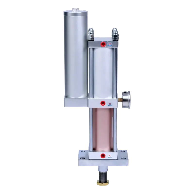
JRA — Standard Pre-Press
| Architecture | Integrated all-in-one |
| Action | Pre-press two-stage |
| Mounting | Vertical (rod down) |
| Output Config | Single output point |
| Force Range | 1 – 40 tons |
| Bore Range | Ø63 – 180 mm |
| Power Stroke | 5 – 50 mm |
- Straight-down press-fitting
- Punching, forming, riveting
- Compact machine integration
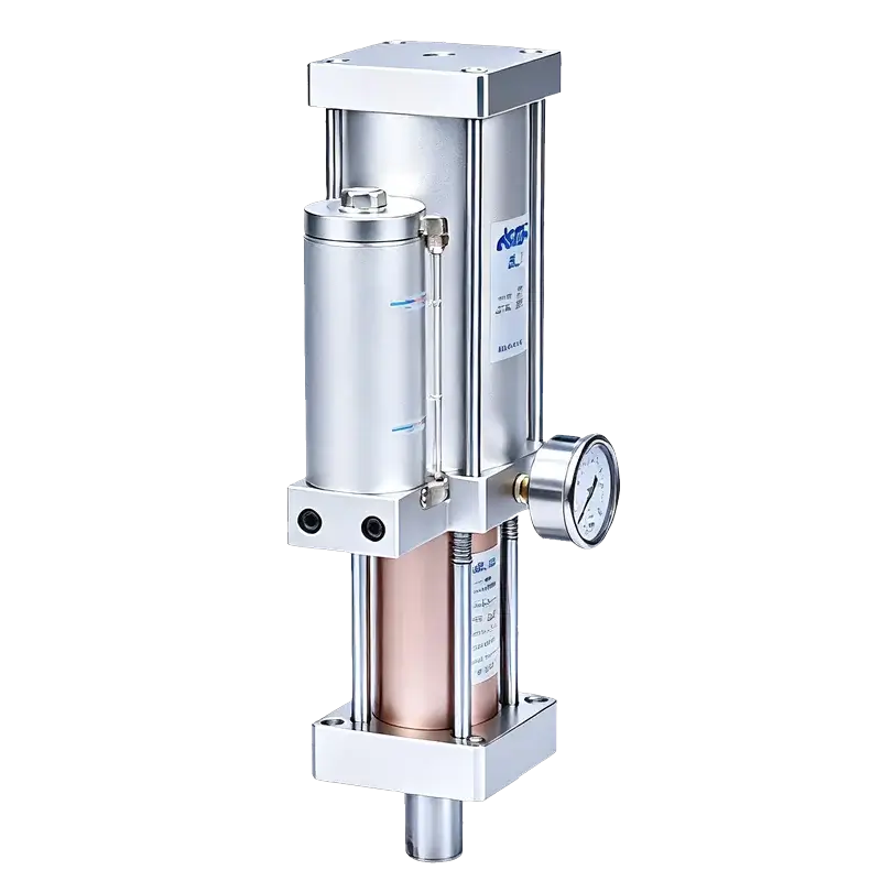
JRE — Direct-Acting
| Architecture | Integrated all-in-one |
| Action | Direct pressure (no pre-press) |
| Mounting | Vertical or horizontal |
| Output Config | Single output point |
| Force Range | 1 – 13 tons |
| Bore Range | Ø50 – 125 mm |
| Speed | 25 – 45 cycles/min |
- Short-stroke, high-cycle tasks
- Marking, embossing, staking
- Simple single-valve control
Build Your Model Number
Select your bore, boost ratio, and matched cylinder configuration. The model code updates instantly — oil displacement is looked up automatically from the ratio × bore matrix.
Configuration Summary
Pre-press stroke and total stroke must be confirmed for final selection. Oil displacement shown is the system reference value from the bore × ratio matrix; high-pressure output per cycle depends on cylinder bore and power-stroke setting.
JRH Selection Guide
Seven parameters define a complete JRH system. Have these ready when you contact our engineering team — or use the model builder above to generate your code.
Booster Air Cylinder Bore
Select from Ø80–180 mm based on required oil volume and available mounting space.
Boost Ratio or Air Stroke
Choose ratio code L07–L41 (7.7:1–41.1:1). Higher ratio = more force but more oil per cycle.
High-Pressure Oil Output
Specify T30 / T50 / T70 / T120 / T170 ml per cycle based on matched cylinder volume.
Pre-Press & Total Stroke
Define the fast approach (pre-press) stroke and total stroke — required for every JRH order.
Matched Cylinder Specs
JRYG cylinder bore (Ø63–125 mm std.), stroke (5–30 mm std.), and quantity (1–3+).
Return Force Requirement
Confirm the JRYG cylinder's return force (120–1000 kg at 6 kgf/cm²) is sufficient for die/mechanism reset.
Oil Lines & Synchronization
Specify oil line length, multi-cylinder synchronization tolerance, and available installation envelope.
Typical Applications
JRH excels where the force must be delivered away from the power source, or where multiple points need simultaneous high force.
Brake & Clutch Systems
Remote cylinders actuate calipers or clutches while the booster stays on the machine frame.
Bearing Press-Fitting
Controlled two-stage force for gentle approach then precise seating of bearings and bushings.
Hardware Assembly
Multi-point riveting, staking, and fastening of hardware fittings with synchronized cylinders.
Extrusion & Bending
High-force forming, bending, and extrusion where the actuator must follow the tool path.
Punching & Deburring
Clean, oil-mist-free operation for punching, trimming, and deburring in production lines.
Marking & Printing
Consistent impact force for part marking, pad printing, and embossing on automated lines.
Resources & Downloads
JRH Catalog Page (PDF)
Full specifications, dimensions, and selection tables from the printed catalog.
Pneumatic Circuit Diagram (DWG/PDF)
Single-cylinder and multi-cylinder circuit drawings, including one-to-four configuration.
3D Models & Engineering Drawings
STEP files and 2D engineering drawings for your selected bore and ratio configuration.
Need Help Configuring Your JRH System?
Send us your workpiece force requirement, available space, and number of actuation points. Our engineering team will recommend the exact bore, ratio, and JRYG cylinder configuration — typically within one business day.