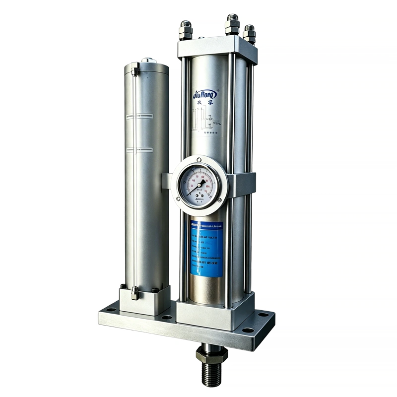
JRP Compact Long-Stroke Hydro-Pneumatic Booster Cylinder
Long approach stroke. Less installation length.
The JRP places the pneumatic and hydraulic cylinders side by side instead of in-line — delivering a long approach stroke with high final force in a significantly shorter axial envelope. Designed for machines where vertical or horizontal mounting length is the limiting constraint.
Why Choose the JRP Compact Long-Stroke Series?
The JRP is JiuRong's side-by-side hydro-pneumatic booster cylinder for machines that need a relatively long approach travel but cannot accommodate the axial installation length of a conventional in-line arrangement. By placing the pneumatic drive cylinder and hydraulic booster cylinder in parallel, the JRP delivers the same long approach stroke and high final force — in a package that is dramatically shorter along the stroke axis.
Conventional In-Line Cylinder
Pneumatic cylinder, oil reservoir, and booster section stack end-to-end — total length grows with stroke.
JRP Side-by-Side Arrangement
Cylinders run in parallel — axial envelope stays compact even at long strokes. Note: lateral width increases.
Compact Axial Envelope
Side-by-side cylinder arrangement reduces total length along the stroke axis — ideal when machine frame height or depth is fixed.
Long Approach Stroke
Total strokes from 50 to 400 mm — the pneumatic approach stage covers long distances quickly at low air consumption before the hydraulic power stroke engages.
High Final Force
1 to 40 tons of high-pressure output from standard 4–7 kgf/cm² (0.4–0.7 MPa) shop air — no hydraulic power unit required.
Fast Cycle Rate
25–45 cycles per minute with approach speeds up to 400 mm/s — the two-stage principle keeps air consumption low while maintaining productivity.
Double-Acting Return
Pneumatic return on both strokes ensures consistent, controlled retraction — no spring fatigue, reliable repeat positioning cycle after cycle.
Proven Two-Stage Principle
Same reliable pneumatic-approach / hydraulic-power-stroke technology as the JRA — just repackaged for constrained envelopes. VG68 anti-wear hydraulic fluid, 0–60°C operating range.
How the JRP Works
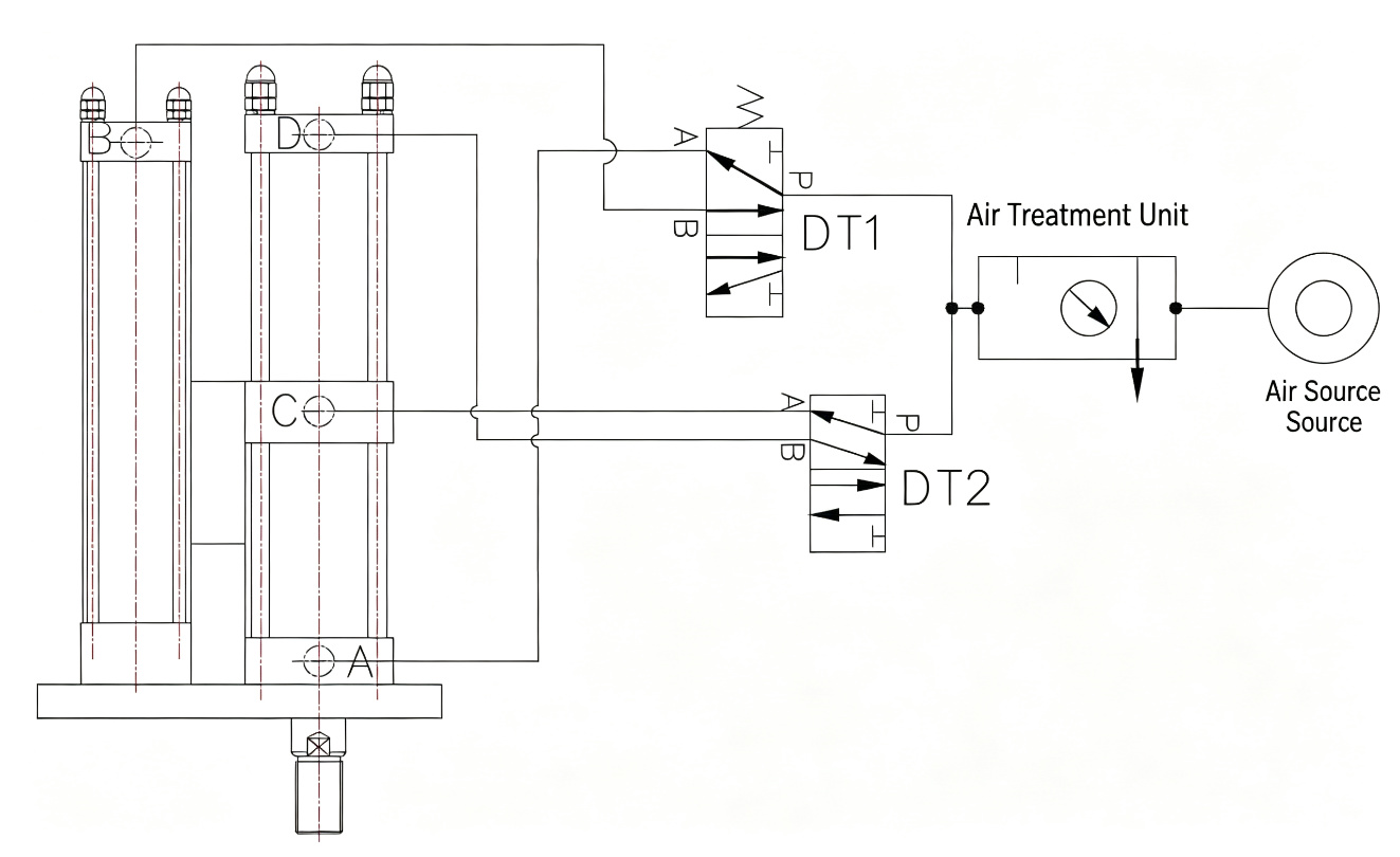
The JRP uses the same two-stage hydro-pneumatic principle as the JRA — a fast low-force pneumatic approach followed by a short high-force hydraulic power stroke. The side-by-side arrangement does not change the operating logic; it only changes the package geometry. Below: the force-displacement profile, the four-step cycle, and the pneumatic circuit that controls it.
Force vs. Displacement Profile
The long approach stage uses only compressed air for rapid traverse. On workpiece contact, the hydraulic booster engages for the final 5–20 mm at full tonnage.
Four-Step Cycle
-
01
Pneumatic Approach
Solenoid valve DT1 energizes. Shop air drives the piston down at high speed (up to 400 mm/s) with low force — covering the full approach stroke with minimal air consumption.
-
02
Workpiece Contact
The ram contacts the workpiece. Pneumatic force alone is insufficient for the operation — this is the trigger point for the hydraulic boost phase.
-
03
Hydraulic Power Stroke
Solenoid valve DT2 energizes. The booster piston pressurizes the hydraulic oil, multiplying force to the rated tonnage (1–40T) for the final 5–20 mm of travel.
-
04
Pressure Release & Return
DT2 de-energizes to release hydraulic pressure, then DT1 de-energizes. The double-acting pneumatic return retracts the ram to home position — ready for the next cycle.
Pneumatic Circuit Diagram
Technical Specifications
Standard JRP series parameters. All models operate on standard shop air (4–7 kgf/cm²) and use VG68 anti-wear hydraulic fluid. Custom bore, stroke, and force configurations available on request.
Performance
- High-pressure output force
- 1–40 tons (nominal)
- Operating air pressure
- 4–7 kgf/cm² (0.4–0.7 MPa / 4–7 bar)
- Bore diameter
- Ø63 / 80 / 100 / 125 / 150 / 160 mm
- Total stroke (approach)
- 50 / 100 / 150 / 200 / 300 / 400 mm
- Power stroke (high-pressure)
- 5 / 10 / 15 / 20 mm
- Cycle rate
- 25–45 cycles / min
- Operating speed
- 50–400 mm/s
- Operating temperature
- 0–60 °C
Construction
- Actuation
- Double-acting
- Cylinder arrangement
- Side-by-side (pneumatic + hydraulic in parallel)
- Hydraulic fluid
- VG68 anti-wear hydraulic oil
- Hydraulic proof pressure
- 120 kgf/cm² (12 MPa)
- Pneumatic proof pressure
- 30 kgf/cm² (3 MPa)
- Mounting orientation
- Vertical, rod-down (standard)
- Rod treatment
- Hardened & ground alloy steel, chrome plated
- Seals
- NBR / polyurethane, service-replaceable
Interface & Control
- Air supply port
- ZG3/8" – ZG1 1/2" (by model)
- Control valves
- Two 5/2-way solenoid valves (DT1, DT2)
- Control voltage
- DC 24 V (standard) / AC 220 V (optional)
- Rod end thread
- M30×1.5 – M100×3 (by model)
- Position sensing
- Magnetic reed / solid-state switches (optional)
- Noise level
- ≤ 75 dB(A) at 1 m
- Lubrication
- Oil-mist lubricator in FRL unit
- Compliance
- ISO 6432 / ISO 15552 mounting patterns
Installation Dimensions
Standard JRP installation dimensions by bore size. Total length (N) varies with power stroke selection (5/10/15/20 mm). All dimensions in mm unless noted. Custom configurations available on request.
Ø63 mm Bore — All Tonnage Options
| Tonnage | A | B | C | D | E | F (Air) | G (Oil) | H | I | J | K | L | M (Thread) | N (5mm) | N (10mm) | N (15mm) | N (20mm) | O | P |
|---|---|---|---|---|---|---|---|---|---|---|---|---|---|---|---|---|---|---|---|
| 5T | 180 | 250 | 100 | 65 | 72 | ZG3/8" | ZG3/8" | 100.5 | 50 | 75 | 35 | 22 | M30x1.5 | 310 | 395 | 480 | 565 | 75 | 95 |
| 10T | 160 | 200 | 100 | 65 | 72 | ZG3/8" | ZG3/8" | 100.5 | 50 | 75 | 35 | 22 | M30x1.5 | 330 | 406 | 482 | 558 | 75 | 95 |
N = total installed length at the selected power stroke (5/10/15/20 mm). All other dimensions are constant regardless of power stroke. Scroll horizontally to view all columns on small screens.
Ø80 mm Bore — All Tonnage Options
| Tonnage | A | B | C | D | E | F (Air) | G (Oil) | H | I | J | K | L | M (Thread) | N (5mm) | N (10mm) | N (15mm) | N (20mm) | O | P |
|---|---|---|---|---|---|---|---|---|---|---|---|---|---|---|---|---|---|---|---|
| 5T | 190 | 310 | 132 | 65 | 89 | ZG3/8" | ZG1/2" | 125 | 50 | 75 | 35 | 25 | M30x1.5 | 380 | 470 | 560 | 650 | 95 | 120 |
| 10T | 190 | 275 | 118 | 65 | 89 | ZG3/8" | ZG1/2" | 125 | 50 | 80 | 40 | 25 | M30x1.5 | 415 | 510 | 605 | 700 | 95 | 120 |
| 15T | 225 | 330 | 145 | 85 | 112 | ZG1/2" | ZG1/2" | 159 | 85 | 110 | 60 | 35 | M40x2 | 493 | 600 | 707 | 814 | 120 | 150 |
N = total installed length at the selected power stroke (5/10/15/20 mm). All other dimensions are constant regardless of power stroke. Scroll horizontally to view all columns on small screens.
Ø100 mm Bore — All Tonnage Options
| Tonnage | A | B | C | D | E | F (Air) | G (Oil) | H | I | J | K | L | M (Thread) | N (5mm) | N (10mm) | N (15mm) | N (20mm) | O | P |
|---|---|---|---|---|---|---|---|---|---|---|---|---|---|---|---|---|---|---|---|
| 10T | 235 | 375 | 170 | 95 | 127 | ZG1/2" | ZG3/4" | 180 | 110 | 135 | 75 | 42 | M42x2 | 598 | 720 | 842 | 964 | 140 | 180 |
| 15T | 200 | 325 | 110 | 85 | 120 | ZG1/2" | ZG3/4" | 169 | 85 | 110 | 60 | 35 | M40x2 | 585 | 710 | 835 | 960 | 120 | 150 |
| 20T | 290 | 400 | 190 | 110 | 157 | ZG3/4" | ZG1" | 220 | 150 | 170 | 90 | 50 | M56x2 | 710 | 855 | 1000 | 1145 | 175 | 220 |
N = total installed length at the selected power stroke (5/10/15/20 mm). All other dimensions are constant regardless of power stroke. Scroll horizontally to view all columns on small screens.
Ø125 mm Bore — All Tonnage Options
| Tonnage | A | B | C | D | E | F (Air) | G (Oil) | H | I | J | K | L | M (Thread) | N (5mm) | N (10mm) | N (15mm) | N (20mm) | O | P |
|---|---|---|---|---|---|---|---|---|---|---|---|---|---|---|---|---|---|---|---|
| 10T | 300 | 460 | 220 | 130 | 182 | ZG3/4" | ZG1" | 257 | 160 | 220 | 120 | 70 | M64x2 | 905 | 1090 | 1275 | 1460 | 240 | 300 |
| 15T | 290 | 400 | 145 | 100 | 148 | ZG1/2" | ZG3/4" | 201 | 110 | 150 | 80 | 45 | M42x2 | 710 | 855 | 1000 | 1145 | 175 | 220 |
| 20T | 300 | 490 | 240 | 140 | 203 | ZG3/4" | ZG1" | 288 | 180 | 240 | 130 | 75 | M64x2 | 970 | 1165 | 1360 | 1555 | 260 | 320 |
N = total installed length at the selected power stroke (5/10/15/20 mm). All other dimensions are constant regardless of power stroke. Scroll horizontally to view all columns on small screens.
Ø150 mm Bore — All Tonnage Options
| Tonnage | A | B | C | D | E | F (Air) | G (Oil) | H | I | J | K | L | M (Thread) | N (5mm) | N (10mm) | N (15mm) | N (20mm) | O | P |
|---|---|---|---|---|---|---|---|---|---|---|---|---|---|---|---|---|---|---|---|
| 20T | 360 | 570 | 290 | 175 | 254 | ZG1" | ZG1 1/4" | 360 | 240 | 310 | 170 | 100 | M80x3 | 1210 | 1450 | 1690 | 1930 | 340 | 420 |
| 30T | 300 | 490 | 200 | 140 | 203 | ZG3/4" | ZG1" | 288 | 180 | 240 | 130 | 75 | M64x2 | 970 | 1165 | 1360 | 1555 | 260 | 320 |
| 40T | 360 | 580 | 300 | 175 | 254 | ZG1" | ZG1 1/4" | 360 | 240 | 310 | 170 | 100 | M80x3 | 1280 | 1530 | 1780 | 2030 | 360 | 440 |
N = total installed length at the selected power stroke (5/10/15/20 mm). All other dimensions are constant regardless of power stroke. Scroll horizontally to view all columns on small screens.
Ø160 mm Bore — All Tonnage Options
| Tonnage | A | B | C | D | E | F (Air) | G (Oil) | H | I | J | K | L | M (Thread) | N (5mm) | N (10mm) | N (15mm) | N (20mm) | O | P |
|---|---|---|---|---|---|---|---|---|---|---|---|---|---|---|---|---|---|---|---|
| 30T | 390 | 660 | 340 | 195 | 284 | ZG1 1/4" | ZG1 1/2" | 403 | 270 | 350 | 195 | 115 | M90x3 | 1450 | 1730 | 2010 | 2290 | 400 | 510 |
| 40T | 420 | 720 | 380 | 220 | 320 | ZG1 1/2" | ZG2" | 455 | 310 | 400 | 225 | 130 | M100x3 | 1650 | 1970 | 2290 | 2610 | 460 | 580 |
N = total installed length at the selected power stroke (5/10/15/20 mm). All other dimensions are constant regardless of power stroke. Scroll horizontally to view all columns on small screens.
Theoretical Output Force vs. Air Pressure
Theoretical high-pressure output force in kgf at various supply pressures. Actual force varies with seal friction, back-pressure, and mechanical efficiency. For critical applications, apply a 0.85 derating factor or contact our engineering team.
| Bore | Nominal Force | 4 kgf/cm² | 5 kgf/cm² | 6 kgf/cm² | 7 kgf/cm² |
|---|---|---|---|---|---|
| Ø63 mm | 5T | 1,800 | 2,250 | 2,700 | 3,150 |
| Ø63 mm | 10T | 3,600 | 4,500 | 5,400 | 6,300 |
| Ø80 mm | 5T | 2,800 | 3,500 | 4,200 | 4,900 |
| Ø80 mm | 10T | 5,600 | 7,000 | 8,400 | 9,800 |
| Ø80 mm | 15T | 8,400 | 10,500 | 12,600 | 14,700 |
| Ø100 mm | 10T | 4,500 | 5,625 | 6,750 | 7,875 |
| Ø100 mm | 15T | 6,750 | 8,438 | 10,125 | 11,813 |
| Ø100 mm | 20T | 9,000 | 11,250 | 13,500 | 15,750 |
| Ø125 mm | 10T | 9,375 | 11,719 | 14,063 | 16,406 |
| Ø125 mm | 15T | 14,063 | 17,578 | 21,094 | 24,609 |
| Ø125 mm | 20T | 18,750 | 23,438 | 28,125 | 32,813 |
| Ø150 mm | 20T | 12,000 | 15,000 | 18,000 | 21,000 |
| Ø150 mm | 30T | 18,000 | 22,500 | 27,000 | 31,500 |
| Ø150 mm | 40T | 24,000 | 30,000 | 36,000 | 42,000 |
| Ø160 mm | 30T | 30,720 | 38,400 | 46,080 | 53,760 |
| Ø160 mm | 40T | 40,960 | 51,200 | 61,440 | 71,680 |
Values are theoretical at 100% efficiency. 1 kgf = 9.807 N. Nominal force ratings are at 6 kgf/cm² supply pressure.
JRP vs. JRA vs. JRE
The choice between JRP, JRA, and JRE depends on your machine envelope, approach stroke length, and whether a pre-press stage is needed. All three deliver hydro-pneumatic force from standard shop air — the difference is packaging and operating mode.
JRP — Compact Long-Stroke
Side-by-side arrangement
- Best for: Machines with limited axial length but available lateral width
- Long approach stroke (50–400 mm) in a short package
- Two-stage: pneumatic approach + hydraulic power stroke
- 1–40T output, double-acting
- Vertical mount, rod-down
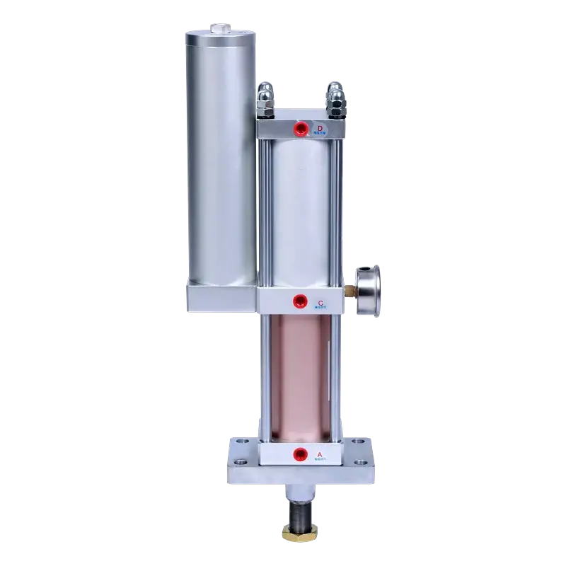
JRA — Standard Pre-Press
In-line arrangement
- Best for: Machines with ample axial installation length
- Same two-stage principle, conventional in-line geometry
- Wider bore and tonnage range
- 1–100T output, vertical or horizontal mount
- Most cost-effective when envelope allows
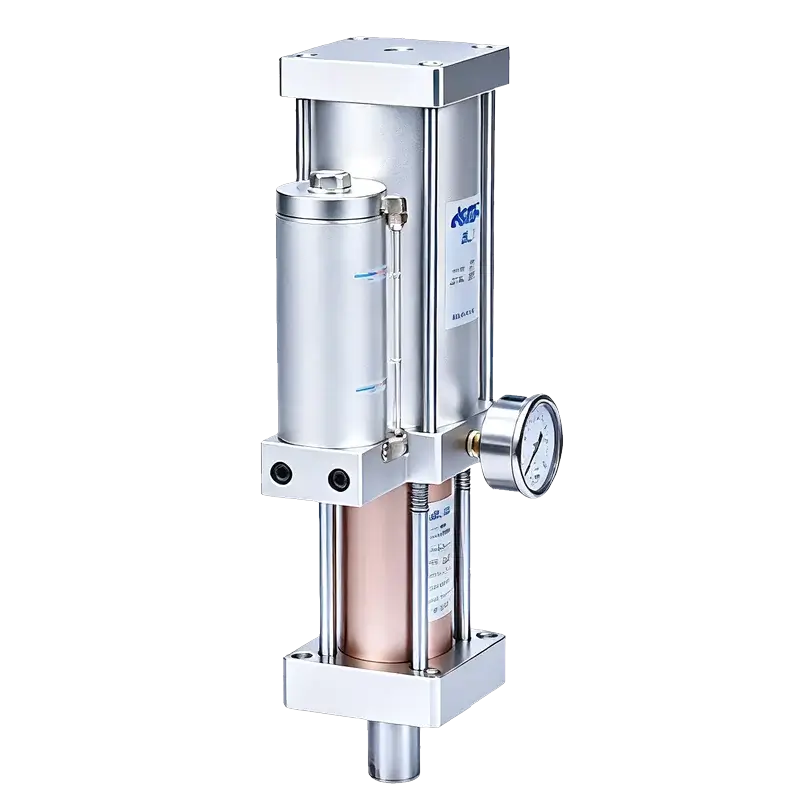
JRE — Direct-Acting
Single-stage, no approach
- Best for: Short-stroke pressing, riveting, marking
- No pre-press / approach stage — direct hydraulic force
- Single solenoid valve, simpler circuit
- 1–13T output, 25–45 cycles/min
- Most compact overall when no approach stroke needed
How to Select a JRP
Follow these seven steps to configure the right JRP for your application. Our engineering team can review your requirements and confirm the selection.
-
1
Check the Installation Envelope
Measure the available axial length (along the stroke direction) and lateral width. The JRP is the right choice when axial length is constrained but lateral space is available. If axial length is not a constraint, the JRA may be more cost-effective.
-
2
Determine Required Force
Calculate the pressing, forming, or joining force your process requires. Select a nominal tonnage that provides at least 15% margin over the calculated requirement. Refer to the force table above for actual output at your shop air pressure.
-
3
Choose Bore Size
Bore determines the available tonnage options. Match the bore to your required force: Ø63 for 5–10T, Ø80 for 5–15T, Ø100 for 10–20T, Ø125 for 10–20T, Ø150 for 20–40T, Ø160 for 30–40T.
-
4
Set Approach Stroke
The total (approach) stroke covers the distance from home position to workpiece contact. Standard options: 50, 100, 150, 200, 300, 400 mm. Choose the shortest stroke that clears your tooling and workpiece — longer strokes increase the N dimension.
-
5
Set Power Stroke
The high-pressure power stroke is the final 5–20 mm where full tonnage is applied. Standard options: 5, 10, 15, 20 mm. This should be just enough to complete the forming, pressing, or joining operation — not the full travel distance.
-
6
Verify Cycle Rate & Duty
The JRP is rated for 25–45 cycles/min. If your application requires sustained high-cycle operation above 40 cycles/min, or continuous duty at maximum force, contact engineering for a high-cycle configuration review.
-
7
Check Return Force & Mounting
Confirm the double-acting pneumatic return can overcome any die spring or stripping force. Verify mounting bolt pattern and rod-end thread (M) match your tooling. Standard mount is vertical, rod-down.
Build Your JRP Model Number
Select your bore, tonnage, and strokes below. The model number updates automatically — use it when requesting a quote.
Where the JRP Fits
The JRP is typically specified when the machine frame has a hard limit on cylinder length along the stroke axis but can accommodate the wider side-by-side profile. Common applications include:
Press Forming
Sheet metal bending, shallow drawing, and profile forming where the ram must travel to the die surface before applying high force — the long approach stroke reaches the workpiece, then the power stroke forms it.
Riveting & Clinching
Self-pierce riveting, solid rivet setting, and sheet-metal clinching. The approach stroke positions the tool, and the short high-force stroke sets the fastener — all within a compact head assembly.
Precision Assembly
Bearing insertion, bushing press-fit, dowel pin installation, and component joining where controlled approach speed prevents part damage before the high-force press-fit stroke.
Press Fitting & Insertion
Inserting threaded inserts, connectors, pins, and seals into housings. The long approach stroke clears fixturing; the power stroke delivers controlled insertion force.
Marking & Stamping
Metal stamping, part marking, and coining operations where the die must descend to the part surface before applying tons of force for a clean impression.
Custom Automation Equipment
Automated assembly lines, rotary index tables, and custom machinery where the cylinder must fit within a predefined head envelope — the JRP's shorter axial length simplifies machine design.
Engineering Boundaries
The JRP is a robust and proven design, but the following conditions require engineering review before final selection. Contact our team with your application details — we will confirm suitability or recommend a modified configuration.
Lateral Loads / Side Force
The rod is designed for axial force only. Guide the tooling separately if the process applies lateral or offset loads to the ram.
Long Stroke + High Cycle Rate
Approach strokes above 200 mm combined with cycle rates above 35/min may require a high-cycle seal package and increased lubrication.
Non-Standard Mounting
Horizontal or angled mounting changes oil distribution and return dynamics. The standard JRP is designed for vertical, rod-down operation.
High-Temperature Environments
Ambient temperatures above 60°C require fluoroelastomer (FKM) seals and high-temperature hydraulic fluid.
Die Spring / Stripping Force
If the return stroke must overcome significant die spring or stripping force, verify the double-acting return capacity at your supply pressure.
Custom Stroke or Force
Strokes beyond 400 mm, force above 40T, or non-standard bore combinations are available as engineered specials — contact us with your requirements.
Frequently Asked Questions
What is the difference between the JRP and a standard JRA cylinder?
The JRP and JRA use the same two-stage hydro-pneumatic principle and deliver the same force range. The difference is the physical arrangement: the JRA stacks the pneumatic cylinder, oil tank, and booster in-line, while the JRP places the pneumatic and hydraulic cylinders side by side. This makes the JRP significantly shorter along the stroke axis but wider laterally. Choose the JRP when axial installation length is constrained; choose the JRA when you have ample vertical or horizontal space and want the most cost-effective option.
Does the JRP require a hydraulic power unit?
No. Like all JiuRong hydro-pneumatic cylinders, the JRP operates entirely from standard compressed air at 4–7 kgf/cm² (0.4–0.7 MPa). The hydraulic oil is sealed inside the cylinder and pressurized by the pneumatic booster piston — no external hydraulic pump, hoses, or power unit is needed.
Can the JRP be mounted horizontally?
The standard JRP is designed for vertical, rod-down mounting. Horizontal or angled installation affects oil distribution and return dynamics. If your application requires non-vertical mounting, contact our engineering team — we can provide a modified configuration or recommend the JRAA (horizontal JRA variant) or JREB (horizontal JRE variant).
How do I choose between JRP and JRE?
Choose the JRE if your application has no approach stroke requirement — the tooling is already close to the workpiece and you only need a short, direct high-force stroke (up to 25 mm). Choose the JRP when you need a long approach stroke (50–400 mm) to reach the workpiece before applying force, but your machine has limited axial length. The JRE is simpler (single valve) and more compact overall; the JRP offers longer reach in a shorter package.
What maintenance does the JRP require?
Routine maintenance is minimal: keep the FRL (filter-regulator-lubricator) supplied with clean air and proper oil-mist lubrication, periodically inspect the air filter element, and check for external oil leaks. The VG68 hydraulic fluid is sealed for life under normal operation; seal replacement is recommended after approximately 2 million cycles or 2 years, whichever comes first. All seals are service-replaceable.
What information do you need to provide a quote?
To quote a JRP, we need: (1) required pressing force in tons, (2) total approach stroke in mm, (3) power stroke in mm, (4) available shop air pressure, (5) mounting orientation, (6) cycle rate (cycles per minute), and (7) application description. You can use the model builder above to generate a model number, then send it to us with your contact details.
Documentation & Support
Need a Compact Long-Stroke Solution?
Send us your JRP model number and application details — our engineering team will confirm the selection and provide a quote within 24 hours.