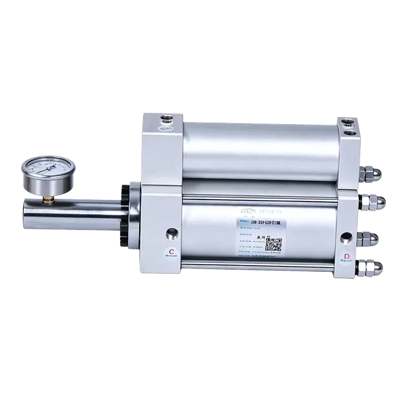
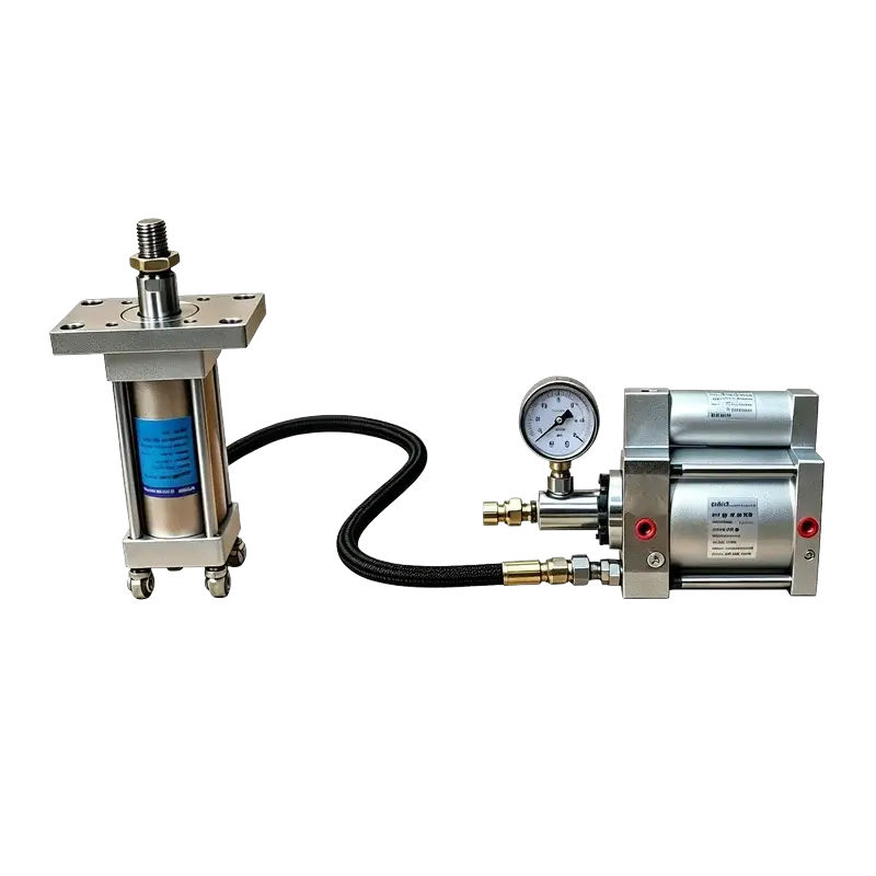
JRU Direct-Acting Hydro-Pneumatic Booster
The simplest boost architecture in the JiuRong line. Single-stage intensification, one solenoid valve, no pre-press approach stroke. Mounts independently and drives one or more remote hydraulic cylinders with pressurised oil.
Why Direct-Acting?
When your cylinder contacts the workpiece immediately — no approach stroke needed — a two-stage booster is over-engineered. JRU strips the architecture to its essence: compressed air in, pressurised oil out, one valve.
Rest → Boost → Return
- One 2-position 5-way solenoid valve
- One PLC output controls the full cycle
- No pre-press stage — instant high-pressure
- Fewer components, fewer failure points
- 30–60 cpm high-frequency cycling
Approach → Boost → Return
- Two solenoid valves (DT1 + DT2)
- Sequenced PLC logic required
- Pre-press approach stroke before boost
- More components, more tuning
- 25–45 cpm typical cycle rate
Single-Valve Control
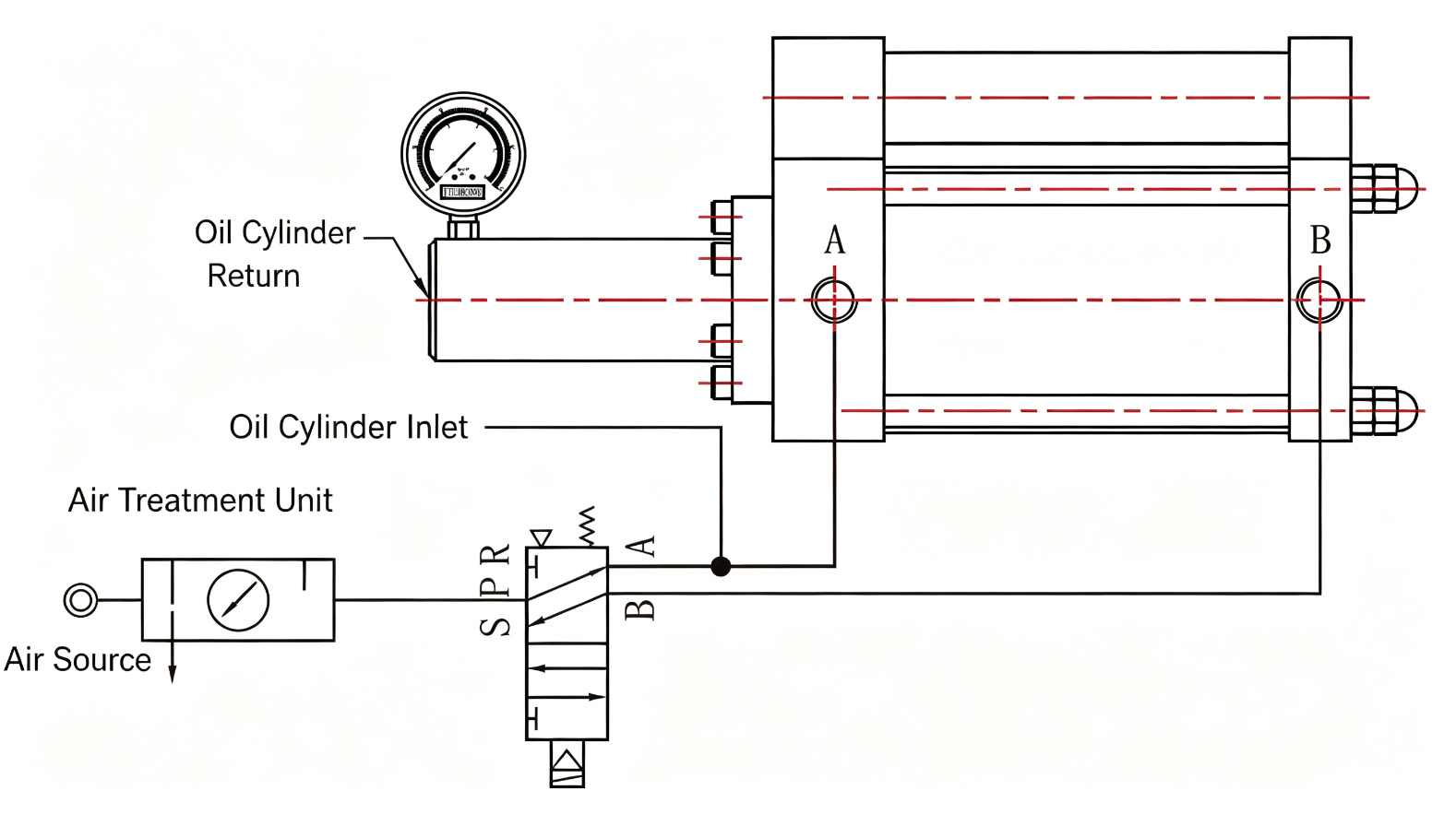
One 2-position 5-way solenoid valve (S/P/R/A/B) manages the complete boost-and-return cycle. One PLC output, no sequencing logic.
Instant High Pressure
No pre-press approach phase. Air pressure directly drives the intensifier piston — pressurised oil is delivered the moment the valve shifts.
Drives Remote Cylinders
Independent foot-mount unit. Connect one or more hydraulic cylinders at the work point — ideal for distributed press systems.
30–60 cpm Fast Cycling
Single-stage action means shorter cycle times. High-frequency operation without oil mist — clean, fast production.
Oil-Mist-Free
Sealed oil circuit eliminates oil mist discharge. Suitable for clean manufacturing environments — brake, clutch, and precision assembly.
7 Boost Ratios
From 7.7:1 to 41.1:1. Match the ratio to your cylinder force requirement and displacement to stroke volume — pay only for what you need.
How It Works
A three-step cycle controlled by a single valve. No pre-press stage, no second solenoid, no sequencing logic.
Rest
Air supply open. The booster sits at return position — the intensifier piston is retracted and the remote cylinder is at home.
Boost
Solenoid DT1 energises. The 5-way valve shifts, directing compressed air to the drive piston. The piston directly intensifies hydraulic oil through the output port to the remote cylinder — high pressure is delivered immediately.
Return
After the set dwell time, DT1 de-energises. The valve springs back, reversing air flow. The drive piston and remote cylinder return to home position simultaneously. Cycle complete.
Output Pressure vs. Time
Solid line: JRU single-stage — pressure rises instantly. Dashed: two-stage boosters spend time on low-pressure approach before boost.
Pneumatic Circuit — Single Valve, Five Ports
Technical Specifications
All values from JiuRong product specification. Operating pressure 4–7 kgf/cm² compressed air.
Performance
| Actuation | Double-acting |
| Operating Pressure | 4–7 kgf/cm² |
| Boost Ratio | 7.7:1 – 41.1:1 (7 options) |
| Oil Displacement | 30 ml – 2000 cc |
| Cycle Rate | 30–60 cycles/min |
| Operating Speed | 50–450 mm/s |
| Proof Pressure | 30 kgf/cm² |
Construction
| Architecture | Direct-acting single-stage |
| Bore Sizes | Ø63 / 80 / 100 / 125 / 160 / 180 mm |
| Mounting | Foot-mount bracket (horizontal) |
| Hydraulic Medium | ISO VG68 anti-wear oil |
| Operating Temp. | 0–60 °C |
| Stroke Tolerance | +0.20 / 0.00 mm |
| Oil Mist | None (sealed circuit) |
Control & Interface
| Control Valve | 1 × 2-position 5-way solenoid |
| Solenoid | DT1 (single) |
| Valve Ports | S / P / R / A / B |
| Air Port Thread | ZG3/8" – ZG1/2" |
| Mounting Thread | M10 – M16 |
| Remote Cylinders | One or more |
| Pressure Gauge | On oil output line |
Installation Dimensions
Select bore size. Dimensions G, H, I, J and oil displacement vary with boost ratio. All dimensions in mm; displacement in cc.
| Boost Ratio | Ratio Value | G (mm) | H (mm) | I (mm) | J (mm) | Oil Disp. (cc) |
|---|---|---|---|---|---|---|
| L07 | 7.7:1 | 700 | 285 | 405 | 588 | 200 |
| L16 | 16.6:1 | 238 | 349 | 434 | 656 | 70 |
| L20 | 20:1 | 253 | 371 | 462 | 698 | 85 |
| L25 | 25.4:1 | 282 | 414 | 515 | 778 | 120 |
| L28 | 28.4:1 | 298 | 438 | 545 | 823 | 138 |
| L36 | 36.4:1 | 323 | 476 | 592 | 894 | 172 |
| L41 | 41.1:1 | 334 | 492 | 612 | 924 | 188 |
| Boost Ratio | Ratio Value | G (mm) | H (mm) | I (mm) | J (mm) | Oil Disp. (cc) |
|---|---|---|---|---|---|---|
| L07 | 7.7:1 | 923 | 362 | 534 | 776 | 350 |
| L16 | 16.6:1 | 263 | 385 | 479 | 724 | 116 |
| L20 | 20:1 | 290 | 424 | 528 | 798 | 140 |
| L25 | 25.4:1 | 325 | 476 | 592 | 894 | 195 |
| L28 | 28.4:1 | 344 | 504 | 627 | 947 | 225 |
| L36 | 36.4:1 | 375 | 549 | 682 | 1030 | 280 |
| L41 | 41.1:1 | 388 | 568 | 706 | 1066 | 304 |
| Boost Ratio | Ratio Value | G (mm) | H (mm) | I (mm) | J (mm) | Oil Disp. (cc) |
|---|---|---|---|---|---|---|
| L07 | 7.7:1 | 1218 | 480 | 706 | 1024 | 700 |
| L16 | 16.6:1 | 380 | 554 | 688 | 1032 | 230 |
| L20 | 20:1 | 422 | 617 | 766 | 1150 | 275 |
| L25 | 25.4:1 | 475 | 695 | 862 | 1294 | 380 |
| L28 | 28.4:1 | 505 | 739 | 916 | 1374 | 438 |
| L36 | 36.4:1 | 550 | 805 | 998 | 1497 | 545 |
| L41 | 41.1:1 | 570 | 834 | 1034 | 1551 | 594 |
| Boost Ratio | Ratio Value | G (mm) | H (mm) | I (mm) | J (mm) | Oil Disp. (cc) |
|---|---|---|---|---|---|---|
| L07 | 7.7:1 | 2326 | 930 | 1358 | 1920 | 1200 |
| L16 | 16.6:1 | 575 | 837 | 1040 | 1560 | 395 |
| L20 | 20:1 | 639 | 933 | 1160 | 1740 | 470 |
| L25 | 25.4:1 | 715 | 1047 | 1302 | 1954 | 650 |
| L28 | 28.4:1 | 760 | 1113 | 1382 | 2074 | 750 |
| L36 | 36.4:1 | 828 | 1212 | 1504 | 2256 | 930 |
| L41 | 41.1:1 | 858 | 1257 | 1560 | 2340 | 1014 |
| Boost Ratio | Ratio Value | G (mm) | H (mm) | I (mm) | J (mm) | Oil Disp. (cc) |
|---|---|---|---|---|---|---|
| L07 | 7.7:1 | 2613 | 1045 | 1524 | 2160 | 2000 |
| L16 | 16.6:1 | 650 | 940 | 1168 | 1752 | 660 |
| L20 | 20:1 | 721 | 1046 | 1302 | 1954 | 790 |
| L25 | 25.4:1 | 808 | 1174 | 1462 | 2194 | 1090 |
| L28 | 28.4:1 | 858 | 1247 | 1552 | 2329 | 1260 |
| L36 | 36.4:1 | 935 | 1359 | 1690 | 2535 | 1565 |
| L41 | 41.1:1 | 968.5 | 1408 | 1752 | 2628 | 1705 |
Ø63 mm bore is available by order. Contact engineering for dimension sheet. Dimensions G–J are overall lengths that vary with boost ratio — confirm with factory drawing before machine integration.
Boost Ratio & Oil Displacement
Output hydraulic pressure = input air pressure × boost ratio. At 6 kgf/cm² supply, output ranges from ~46 to ~247 kgf/cm². Oil displacement must cover your cylinder stroke volume × number of cylinders.
| Ratio Code | Boost Ratio | Output @ 6 kgf/cm² | Ø80 | Ø100 | Ø125 | Ø160 | Ø180 |
|---|---|---|---|---|---|---|---|
| L07 | 7.7:1 | ~46 kgf/cm² | 200 cc | 350 cc | 700 cc | 1200 cc | 2000 cc |
| L16 | 16.6:1 | ~100 kgf/cm² | 70 cc | 116 cc | 230 cc | 395 cc | 660 cc |
| L20 | 20:1 | ~120 kgf/cm² | 85 cc | 140 cc | 275 cc | 470 cc | 790 cc |
| L25 | 25.4:1 | ~152 kgf/cm² | 120 cc | 195 cc | 380 cc | 650 cc | 1090 cc |
| L28 | 28.4:1 | ~170 kgf/cm² | 138 cc | 225 cc | 438 cc | 750 cc | 1260 cc |
| L36 | 36.4:1 | ~218 kgf/cm² | 172 cc | 280 cc | 545 cc | 930 cc | 1565 cc |
| L41 | 41.1:1 | ~247 kgf/cm² | 188 cc | 304 cc | 594 cc | 1014 cc | 1705 cc |
Output pressure is theoretical (supply pressure × ratio). Actual pressure depends on line losses, cylinder load, and pressure switch setting. Oil displacement values are per boost stroke at full ratio.
JRU vs JRH vs JRA
Three architectures for different machine layouts. The decision comes down to two questions: do you need a pre-press approach stroke, and can the cylinder be integrated?
Direct-Acting Booster
- Stages: Single-stage (no approach)
- Valves: 1 solenoid
- Cylinder: Remote (one or more)
- Cycle: 30–60 cpm
- Best for: Brake/clutch, bearing press, simple assembly, multi-point systems
Pre-Press Booster
- Stages: Two-stage (approach + boost)
- Valves: 2 solenoids (DT1 + DT2)
- Cylinder: Remote
- Cycle: 25–45 cpm
- Best for: Applications needing fast approach before high-pressure forming
Integrated Cylinder
- Stages: Two-stage (pre-press + boost)
- Valves: 2 solenoids
- Cylinder: Integrated (self-contained)
- Cycle: 25–45 cpm
- Best for: Single press point where cylinder mounts directly at the work station
How to Select Your JRU
Four parameters determine your model: bore, boost ratio, oil displacement, and mounting. Work through them in order.
-
1
Confirm Direct-Acting Is Right
Does your cylinder contact the workpiece immediately — no gap to close first? If yes, JRU single-stage is the simplest choice. If you need a fast low-pressure approach before boost, choose JRH.
-
2
Calculate Required Boost Ratio
Ratio = required hydraulic pressure ÷ available air pressure. Example: need 150 kgf/cm² at 6 kgf/cm² supply → ratio 25:1 → select L25 (25.4:1). Round up to the next standard ratio.
-
3
Size Oil Displacement
Displacement must fill the remote cylinder(s) for the full power stroke: cylinder bore area × stroke × number of cylinders. Add 10–15% margin. Match to the displacement table for your bore and ratio.
-
4
Pick Bore Size
Bore determines the physical size and displacement range. Larger bores deliver more oil per stroke. Ø80–100 suits small cylinders; Ø125–180 for larger or multiple cylinders.
-
5
Verify Dimensions & Mounting
Check the dimension table for your bore/ratio combination. Confirm foot-mount hole pattern fits your machine frame. Allow space for oil lines to the remote cylinder(s).
-
6
Check Cycle Rate
JRU cycles at 30–60 cpm (inversely proportional to stroke/displacement). Confirm your production rate falls within range. Higher ratios with larger displacement cycle slower.
Build Your Model Number
Select your bore, boost ratio, and oil displacement below. The model number updates automatically — use it when requesting a quote.
Applications
JRU serves applications where the cylinder contacts the workpiece immediately and the booster can be mounted remotely from the work point.
Brake & Clutch Actuation
Direct boost to engage brakes or clutches. No approach stroke needed. Single-valve control integrates with machine safety logic. Oil-mist-free for clean environments.
Bearing Press-Fit
Press bearings directly into housings. Consistent pressurised oil to the remote cylinder. One signal triggers the complete press cycle — repeatable, high-frequency.
Hardware Assembly
Riveting, staking, and fastening operations. Fast cycle rates (30–60 cpm) support high-volume assembly lines. Stable output extends tooling life.
Multi-Point Clamping
One booster drives multiple clamp cylinders through a common oil circuit. Single valve, single PLC output — simplest way to power distributed workholding.
High-Frequency Production Cells
Short, repeatable boost cycles at 30–60 cpm. No oil mist means no extraction required — ideal for automated cells with sensitive electronics nearby.
Simple Press Stations
Any station needing a compact pressurised-oil source without a full hydraulic power unit. Lower cost, lower noise, lower maintenance than a pump-and-tank system.
Engineering Boundaries
Conditions that require review or a different product. Specifying within these limits ensures reliable operation.
Pre-Press Stroke Required
JRU has no approach stage. If the cylinder must travel to the workpiece before high-pressure boost, choose JRH (two-stage separated) or JRA (integrated).
Air Pressure Outside 4–7 kgf/cm²
Output pressure scales with supply pressure. Below 4 kgf/cm² the booster may not reach rated force; above 7 kgf/cm² exceeds design limits. Use a regulator if shop air is higher.
Displacement Mismatch
Oil displacement must exceed the total cylinder volume (bore area × stroke × cylinder count). Under-sizing causes incomplete stroke. Over-sizing wastes air and slows cycling.
Long Oil Lines
Remote cylinder distance affects response time and line loss. For lines over 3 m, or with multiple cylinders, contact engineering for line sizing and synchronisation review.
Temperature & Fluid
Operating range 0–60 °C with ISO VG68 anti-wear hydraulic oil. Other fluids (water-glycol, synthetic) require seal material review — consult factory.
Proof Pressure Limit
Air cylinder proof pressure is 30 kgf/cm². Never exceed rated supply pressure. The high-pressure oil side is designed for the rated boost output — do not dead-head without a relief valve.
Frequently Asked Questions
Answers to the questions engineers ask most often about direct-acting boosters.
What is a direct-acting hydro-pneumatic booster?
A direct-acting (single-stage) booster uses compressed air to directly drive an intensifier piston that pressurises hydraulic oil. There is no separate pre-press approach stroke — high-pressure oil is delivered the moment the valve shifts. It is the simplest hydro-pneumatic boost architecture.
How does JRU differ from JRH?
JRU is single-stage: one valve, three steps (rest → boost → return), no approach stroke. JRH is two-stage: two valves, four steps (approach → pre-press → boost → return), with a low-pressure approach before high-pressure. Choose JRU when the cylinder contacts the workpiece immediately; choose JRH when it needs to travel to the workpiece first.
Can one JRU drive multiple hydraulic cylinders?
Yes. JRU is a standalone booster that outputs pressurised oil to a common circuit. One or more remote cylinders can be connected, provided the total oil volume (bore area × stroke × cylinder count) is within the booster's displacement rating. For synchronised multi-cylinder operation, contact engineering for line balancing review.
How do I choose the right boost ratio?
Divide your required hydraulic pressure by your available air pressure. For example, if you need 150 kgf/cm² and your shop air is 6 kgf/cm², the ratio is 25:1 — select L25 (25.4:1). Always round up to the next standard ratio. The seven options range from 7.7:1 (L07) to 41.1:1 (L41).
What does oil displacement mean and how do I size it?
Oil displacement is the volume of high-pressure oil the booster delivers per stroke, measured in cc or ml. It must fill your remote cylinder for the full power stroke: displacement = cylinder bore area × stroke length. For multiple cylinders, multiply by the number of cylinders and add 10–15% margin.
Why does JRU cycle faster than two-stage boosters?
Single-stage architecture eliminates the approach stroke and the second valve-switching event. The piston goes directly to boost and returns — fewer steps per cycle means 30–60 cpm versus 25–45 cpm for two-stage units. Actual rate depends on ratio, displacement, and line length.
Does JRU produce oil mist?
No. The hydraulic oil is contained in a sealed circuit between the booster and the remote cylinder(s). Unlike open pneumatic systems, there is no oil-laden exhaust. This makes JRU suitable for clean manufacturing environments, electronics-adjacent cells, and food-grade-adjacent areas.
Is JRU a booster or a booster cylinder?
JRU is a booster (intensifier) — not an integrated booster cylinder. It is a standalone unit that outputs pressurised oil to a separate hydraulic cylinder. Products like JRA through JRG are integrated booster cylinders where the air and oil sections are in one body. JRU is chosen when the booster and work cylinder must be physically separated.
Need a Simple Boost Source?
Send us your required boost ratio, oil displacement, and remote cylinder details. Our engineering team will confirm the selection and provide a quote within 24 hours.