JRV Direct-Acting Flange-Mount Booster System
A complete air-hydraulic intensifier package — booster body, matched JRYG cylinder(s), and high-pressure oil line — shipped under one combined order code. Single-stage direct-acting architecture, one solenoid valve, zero pre-press stroke. Just connect air and go.
Why Order a Packaged Booster System?
The JRV is not a new intensifier principle — it is the proven JRU direct-acting architecture delivered as a flange-mount, factory-matched set. One order number, one compatibility guarantee, one installation.
- Risk of oil-volume mismatch — booster output vs. cylinder displacement
- Separate POs, separate lead times, separate QC
- Flange or foot-mount compatibility verified on site
- Hydraulic fittings and hose sourced separately
- Oil displacement pre-calculated against JRYG cylinder bore × stroke
- Booster, cylinder(s), and high-pressure hose arrive as one set
- Flange mounting (FA/FB) selected at order time — bolt-on ready
- Factory-tested connection; no guesswork on fittings
One Combined Code
JR-V booster code + JR-YG cylinder code in a single order string. No separate BOM management.
Flange Mount
JRYG cylinders mount via front (FA) or rear (FB) flange — precise axial alignment, compact footprint.
Guaranteed Match
Booster oil output is sized to the selected cylinder(s). No under-stroke or oil starvation at full pressure.
Single-Valve Control
One 2-position 5-way solenoid valve drives the entire cycle — fewer failure points than pre-press designs.
1 to 3 Cylinders
Drive one, two, or three matched JRYG cylinders from a single booster — distributed or synchronous force.
ISO 9001 Built
Manufactured under ISO 9001:2015 quality system. 2-year warranty. Non-standard customization available.
How the JRV System Works
The JRV uses the same single-stage direct-acting principle as the JRU. Compressed air drives the booster piston, which pressurizes hydraulic oil and sends it through the high-pressure line to the matched JRYG cylinder(s). Three steps, one valve.
Rest
Solenoid de-energized. Shop air holds the booster piston at home position. The JRYG cylinder rod is retracted. System is idle, ready for cycle start.
Boost
Valve shifts. Air enters the booster drive chamber, pushing the intensifier piston forward. Oil pressure rises to Psupply × boost ratio and flows to the JRYG cylinder, extending the rod at high force.
Return
Valve shifts back. Air reverses, retracting the booster piston. Oil flows back from the JRYG cylinder, and the rod retracts. System returns to rest.
Pressure Profile (Single-Stage Direct-Acting)
No approach stroke — full pressure is available the moment the valve shifts. Ideal for short, high-force operations where rapid approach is not required.
Pneumatic Circuit (Single 2-Position 5-Way Valve)
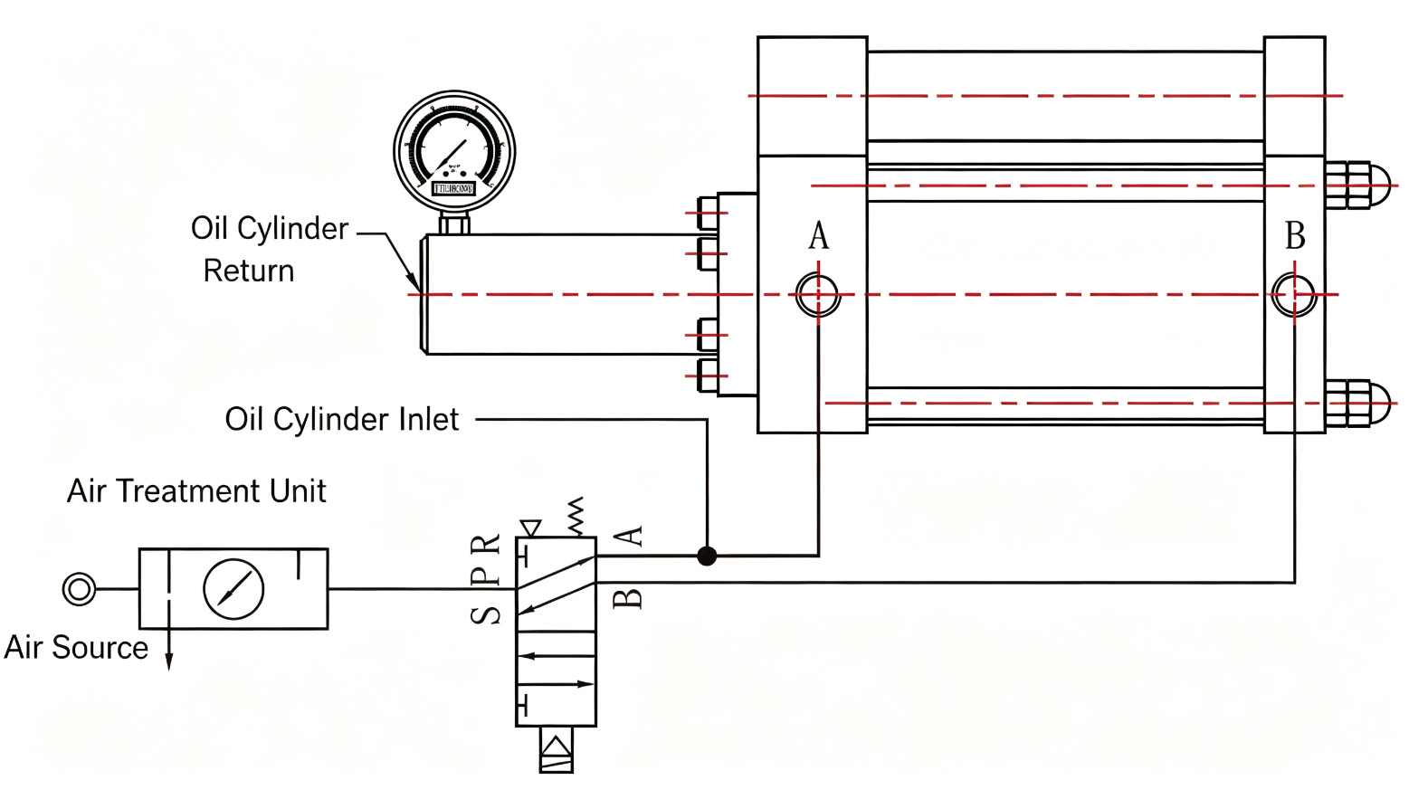
The JRV shares the JRU single-valve circuit: FRL → 2-position 5-way solenoid (S/P/R/A/B ports) → booster → high-pressure oil line → JRYG cylinder(s) with pressure gauge. Actual project piping diagram provided with order.
What's in the System
Every JRV order includes two matched components connected by a factory-supplied high-pressure oil line.
JRV Booster Body
Single-stage direct-acting air-hydraulic intensifier. Converts 4–7 kgf/cm² shop air into high-pressure oil at the selected boost ratio (7.7:1 to 41:1). Flange-mount design with integrated pressure gauge.
- Bores: Ø63 / 80 / 100 / 125 / 160 mm
- Oil output: 30–200 ml
- Max output pressure: up to ~246 kgf/cm²
- Control: single 5/2 solenoid valve
Matched JRYG Cylinder(s)
Flange-mount hydraulic cylinder(s) sized to the booster's oil output. Available with front flange (FA) or rear flange (FB) mounting. Order 1, 2, or 3 cylinders per booster.
- Bores: Ø63 / 80 / 100 / 125 mm (150/160 on request)
- Strokes: 5 / 10 / 20 / 30 mm (up to 400 mm on request)
- Mounting: FA (front flange) or FB (rear flange)
- Return force: 120–1,000 kgf at 6 kgf/cm²
Technical Specifications
Combined performance data for the JRV booster and matched JRYG cylinder(s).
Booster (JR-V)
| Type | Single-stage direct-acting air-hydraulic intensifier |
| Operating pressure | 4–7 kgf/cm² |
| Boost ratios | 7.7:1 – 41:1 (7 options) |
| Max oil output | 30–200 ml |
| Booster bores | Ø63 / 80 / 100 / 125 / 160 mm |
| Action | Double-acting |
| Working speed | 50–450 mm/s |
| Cycle rate | 30–60 cycles/min |
| Hydraulic fluid | VG68 anti-wear hydraulic oil |
| Operating temp | 0–60 °C |
| Proof pressure | 30 kgf/cm² (air side) |
| Control valve | Single 2-position 5-way solenoid |
JRYG Cylinder
| Cylinder bores | Ø63 / 80 / 100 / 125 mm |
| Standard strokes | 5 / 10 / 20 / 30 mm |
| Optional strokes | 50 / 100 / 150 / 200 / 300 / 400 mm |
| Mounting style | FA (front flange) / FB (rear flange) |
| Cylinders per booster | 1, 2, or 3 |
| Return force @ 6 kgf/cm² | 120–560 kgf (Ø63–125) |
| Rod thread | M30×1.5 – M48×2 |
| Oil port | ZG3/8" – ZG3/4" |
| Seals | NOK / Parker high-pressure seals |
System
| Order format | Combined JR-V + JR-YG code |
| Connection | High-pressure oil hose (included) |
| Pressure gauge | Included on booster |
| Air supply | Clean, dry compressed air via FRL |
| Warranty | 2 years |
| Certification | ISO 9001:2015 |
| Customization | Non-standard bores, strokes, mounts |
| Lead time | Contact factory |
Installation Dimensions
JRYG cylinder flange and body dimensions. Booster body dimensions reference the JRU series (same direct-acting body).
JRYG Cylinder Dimensions (mm)
| K Flange W |
L Flange L |
T Flange T |
M Hole C-C |
N Hole C-C |
O Hole Ø |
V Tube Ø |
Q | R | P Rod Thread |
U Overall L |
X End Cap |
W Oil Port |
Return Force @6 kgf/cm² |
|---|---|---|---|---|---|---|---|---|---|---|---|---|---|
| 160 | 100 | 22 | 132 | 65 | 14 | 75 | 50 | 35 | M30×1.5 | 177 | 95 | ZG3/8" | 120 kgf |
Ø150 and Ø160 bores available on request. All dimensions in mm unless noted. Confirm certified drawing with factory before machining mounting features.
| K Flange W |
L Flange L |
T Flange T |
M Hole C-C |
N Hole C-C |
O Hole Ø |
V Tube Ø |
Q | R | P Rod Thread |
U Overall L |
X End Cap |
W Oil Port |
Return Force @6 kgf/cm² |
|---|---|---|---|---|---|---|---|---|---|---|---|---|---|
| 190 | 118 | 25 | 155 | 87 | 17 | 90 | 55 | 40 | M30×1.5 | 190 | 110 | ZG1/2" | 220 kgf |
Ø150 and Ø160 bores available on request. All dimensions in mm unless noted. Confirm certified drawing with factory before machining mounting features.
| K Flange W |
L Flange L |
T Flange T |
M Hole C-C |
N Hole C-C |
O Hole Ø |
V Tube Ø |
Q | R | P Rod Thread |
U Overall L |
X End Cap |
W Oil Port |
Return Force @6 kgf/cm² |
|---|---|---|---|---|---|---|---|---|---|---|---|---|---|
| 225 | 145 | 30 | 190 | 110 | 22 | 100 | 55 | 45 | M40×2 | 200 | 140 | ZG1/2" | 370 kgf |
Ø150 and Ø160 bores available on request. All dimensions in mm unless noted. Confirm certified drawing with factory before machining mounting features.
| K Flange W |
L Flange L |
T Flange T |
M Hole C-C |
N Hole C-C |
O Hole Ø |
V Tube Ø |
Q | R | P Rod Thread |
U Overall L |
X End Cap |
W Oil Port |
Return Force @6 kgf/cm² |
|---|---|---|---|---|---|---|---|---|---|---|---|---|---|
| 235 | 160 | 35 | 255 | 140 | 25 | 120 | 75 | 60 | M48×2 | 225 | 150 | ZG3/4" | 560 kgf |
Ø150 and Ø160 bores available on request. All dimensions in mm unless noted. Confirm certified drawing with factory before machining mounting features.
| K Flange W |
L Flange L |
T Flange T |
M Hole C-C |
N Hole C-C |
O Hole Ø |
V Tube Ø |
Q | R | P Rod Thread |
U Overall L |
X End Cap |
W Oil Port |
Return Force @6 kgf/cm² |
|---|---|---|---|---|---|---|---|---|---|---|---|---|---|
| 320 | 200 | 40 | 260 | 140 | 32 | 130 | 75 | 60 | M48×2 | 265 | 200 | ZG3/4" | 890 kgf |
Ø150 and Ø160 bores available on request. All dimensions in mm unless noted. Confirm certified drawing with factory before machining mounting features.
| K Flange W |
L Flange L |
T Flange T |
M Hole C-C |
N Hole C-C |
O Hole Ø |
V Tube Ø |
Q | R | P Rod Thread |
U Overall L |
X End Cap |
W Oil Port |
Return Force @6 kgf/cm² |
|---|---|---|---|---|---|---|---|---|---|---|---|---|---|
| 350 | 220 | 50 | 290 | 140 | 40 | 130 | 80 | 60 | M56×2 | 270 | 220 | ZG3/4" | 1000 kgf |
Ø150 and Ø160 bores available on request. All dimensions in mm unless noted. Confirm certified drawing with factory before machining mounting features.
Booster body dimensions: The JRV booster shares the JRU direct-acting body. For Ø80–Ø160 booster bore dimensions (A–F fixed dimensions and G–J ratio-dependent lengths), refer to the JRU dimension table. Ø63 booster dimensions available on request.
Boost Ratio & Output Pressure
Output oil pressure at 6 kgf/cm² supply air. Actual pressure scales linearly with supply pressure (4–7 kgf/cm²).
| Ratio Code | Boost Ratio | Output Pressure @ 6 kgf/cm² | Output @ 5 kgf/cm² | Output @ 7 kgf/cm² | Typical Application |
|---|---|---|---|---|---|
| L07 | 7.7:1 | ~46 kgf/cm² | ~39 kgf/cm² | ~54 kgf/cm² | Light clamping, positioning |
| L16 | 16:1 | ~96 kgf/cm² | ~80 kgf/cm² | ~112 kgf/cm² | Medium pressing, bearing fit |
| L20 | 20:1 | ~120 kgf/cm² | ~100 kgf/cm² | ~140 kgf/cm² | General-purpose press-fit |
| L25 | 25:1 | ~150 kgf/cm² | ~125 kgf/cm² | ~175 kgf/cm² | Metal forming, riveting |
| L28 | 28.4:1 | ~170 kgf/cm² | ~142 kgf/cm² | ~199 kgf/cm² | High-force assembly |
| L36 | 36:1 | ~216 kgf/cm² | ~180 kgf/cm² | ~252 kgf/cm² | Heavy stamping, punching |
| L41 | 41:1 | ~246 kgf/cm² | ~205 kgf/cm² | ~287 kgf/cm² | Maximum-force operations |
Output pressure = supply pressure × boost ratio (theoretical). Actual output may be 5–10% lower due to seal friction. Oil displacement (30–200 ml) must be matched to JRYG cylinder bore × stroke × quantity.
JRV vs JRU vs JRH
Choose the right intensifier architecture for your application.
Flange-Mount Packaged System
One order, complete set
- Architecture: Single-stage direct-acting
- Pre-press stroke: None
- Mounting: Flange (FA/FB)
- Cylinders: 1–3 matched JRYG included
- Order: Combined code (booster + cylinders)
- Best for: Drop-in replacement, guaranteed compatibility, multi-cylinder setups
Standalone Booster
Build your own system
- Architecture: Single-stage direct-acting
- Pre-press stroke: None
- Mounting: Foot-mount bracket
- Cylinders: Sourced separately
- Order: Booster only
- Best for: Custom integrations, 4+ cylinders, existing hydraulic circuits
Pre-Press Separated Booster
Two-stage with approach stroke
- Architecture: Two-stage (pre-press + boost)
- Pre-press stroke: Yes (long approach)
- Mounting: Separated body
- Cylinders: Matched JRYG optional
- Order: Booster or combined
- Best for: Long approach + high-force final stroke (die spotting, deep press)
How to Select Your JRV System
Six steps to a complete, matched order code.
-
1
Confirm direct-acting fit
JRV has no approach stroke — full force starts immediately. If you need fast, low-force approach before high force, consider the JRH pre-press series instead.
-
2
Calculate required output force
Determine the pressing force (kgf or kN) your operation needs. Output pressure = supply air × boost ratio; force = output pressure × cylinder piston area.
-
3
Pick boost ratio and oil displacement
Select a ratio (L07–L41) that delivers the required pressure at your shop air pressure. Ensure the booster's oil output (30–200 ml) exceeds the JRYG cylinder's swept volume × cylinder count.
-
4
Choose JRYG cylinder bore and stroke
Match cylinder bore to desired force output and stroke to your work travel. Standard strokes: 5/10/20/30 mm. Longer strokes (up to 400 mm) on request.
-
5
Select flange mounting and cylinder count
FA (front flange) for compact top-mount; FB (rear flange) for through-mount. Specify 1, 2, or 3 cylinders per booster.
-
6
Verify and request quote
Use the model builder below to generate your combined order code. Send it to our engineering team for confirmation and lead time.
Build Your Model Number
Select your booster and cylinder options to generate the combined JRV order code.
Booster (JR-V)
JRYG Cylinder(s)
Estimated Output
Applications
The JRV packaged system is ideal for OEMs and integrators who need a bolt-on high-force solution without designing their own hydraulic circuit.
Bearing & Bushing Press-Fit
Controlled high force for precise bearing insertion. Flange mount bolts directly to fixture plates.
Hardware Assembly
Riveting, staking, and fastening operations requiring repeatable force in compact spaces.
Brake & Clutch Systems
Industrial brake and clutch actuation where remote cylinders and single-valve control simplify plumbing.
Multi-Point Clamping
One booster driving 2–3 JRYG cylinders for synchronous or distributed workholding.
Fixture & Jig Clamping
Flange-mount cylinders integrate directly into welding fixtures, machining jigs, and assembly stations.
Die Casting Ejection
High-force ejection in die-casting and molding operations where packaged reliability matters.
Engineering Boundaries
Conditions that require engineering review before ordering.
Output pressure scales directly with supply. Below 4 kgf/cm² force may be insufficient; above 7 kgf/cm² requires a regulator and may reduce seal life.
JRYG cylinders offer strokes up to 400 mm on request, but booster oil displacement must be re-verified. Long strokes may require a larger booster or JRH pre-press architecture.
JRV supports 1–3 matched cylinders. For 4+ remote cylinders, use the JRU standalone booster with custom manifold design.
Direct-acting design delivers full pressure immediately with no low-force approach. If your application requires rapid traverse before high force, the JRH two-stage pre-press booster is the correct choice.
Sustained cycling above 60 cycles/min generates heat and accelerates seal wear. Contact engineering for high-cycle configurations.
Standard seals suit VG68 anti-wear hydraulic oil at 0–60°C. Water-glycol, phosphate ester, corrosive, or washdown environments require custom seals and coatings.
Frequently Asked Questions
Answers to common questions about the JRV flange-mount booster system.
What is the difference between JRV and JRU?
The JRV and JRU share the same single-stage direct-acting intensifier architecture. The difference is in packaging and mounting: the JRV is a flange-mount system that ships as a complete set (booster + matched JRYG cylinder(s) + high-pressure hose) under one combined order code, while the JRU is a standalone foot-mount booster that you pair with your own cylinders. Choose JRV for a guaranteed-compatible, bolt-on solution; choose JRU when you need to integrate with existing hydraulic circuits or drive more than three cylinders.
Does the JRV come with cylinders included?
Yes. Every JRV order includes the booster body, one to three matched JRYG flange-mount hydraulic cylinders, and the high-pressure oil line connecting them. The combined order code (JR-V-... 配 JR-YG-...) specifies both the booster and cylinder configuration in one string, ensuring factory-verified compatibility.
How do I order a complete JRV system?
Use the model builder on this page to select: booster bore, boost ratio, oil displacement, JRYG cylinder bore, cylinder stroke, and cylinder quantity. The builder generates a combined code like JR-V-80-L20-T30ml 配 JR-YG-63-20-1. Send this code to our engineering team for confirmation and a quotation. You can also request FA (front flange) or FB (rear flange) mounting for the JRYG cylinders.
Can one JRV booster drive multiple cylinders?
Yes. The JRV supports 1, 2, or 3 matched JRYG cylinders per booster. The booster's oil displacement must exceed the total swept volume of all cylinders (bore area × stroke × quantity). The model builder above calculates this automatically and warns if the selected displacement is insufficient.
What is the maximum output pressure?
At 6 kgf/cm² supply air, output oil pressure ranges from approximately 46 kgf/cm² (L07, 7.7:1 ratio) to 246 kgf/cm² (L41, 41:1 ratio). Output scales linearly with supply pressure within the 4–7 kgf/cm² range. Actual force at the cylinder rod depends on the JRYG cylinder bore.
Does the JRV have a pre-press (approach) stroke?
No. The JRV uses single-stage direct-acting architecture — full hydraulic pressure is available the moment the solenoid valve shifts, with no low-force approach stroke. This makes it ideal for short, high-force operations. If you need a fast, low-force approach before high-force pressing, consider the JRH two-stage pre-press booster instead.
What is the difference between FA and FB mounting?
FA is front-flange mounting: the flange is on the rod end of the JRYG cylinder, suitable for top-mount or face-mount installations where the cylinder extends through a fixture plate. FB is rear-flange mounting: the flange is on the cap end, used for through-mount or rear-mount configurations. Both provide precise axial alignment and a compact footprint compared to foot-mount brackets.
What kind of valve does the JRV require?
The JRV uses a single 2-position 5-way solenoid valve (S/P/R/A/B ports) — the same simple circuit as the JRU. One valve controls the entire boost-and-return cycle. FRL (filter-regulator-lubricator) is required on the air supply. No second valve or pre-press logic is needed.
Resources & Related Products
JRU Standalone Booster
Same direct-acting architecture in foot-mount standalone form — for custom integrations and 4+ cylinder setups.
All HPC Products
Compare the full JiuRong hydro-pneumatic cylinder and booster lineup: JRA, JRE, JRP, JRT, JRU, JRV, JRH and more.
Request Engineering Support
Need help sizing a JRV system? Send your application details and our engineers will recommend a configuration.
Ready to Configure Your JRV System?
Send us your combined order code or application requirements. Our engineering team will confirm compatibility, dimensions, and lead time — usually within one business day.