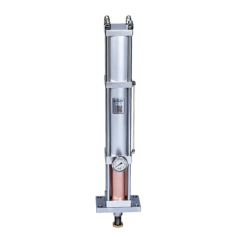
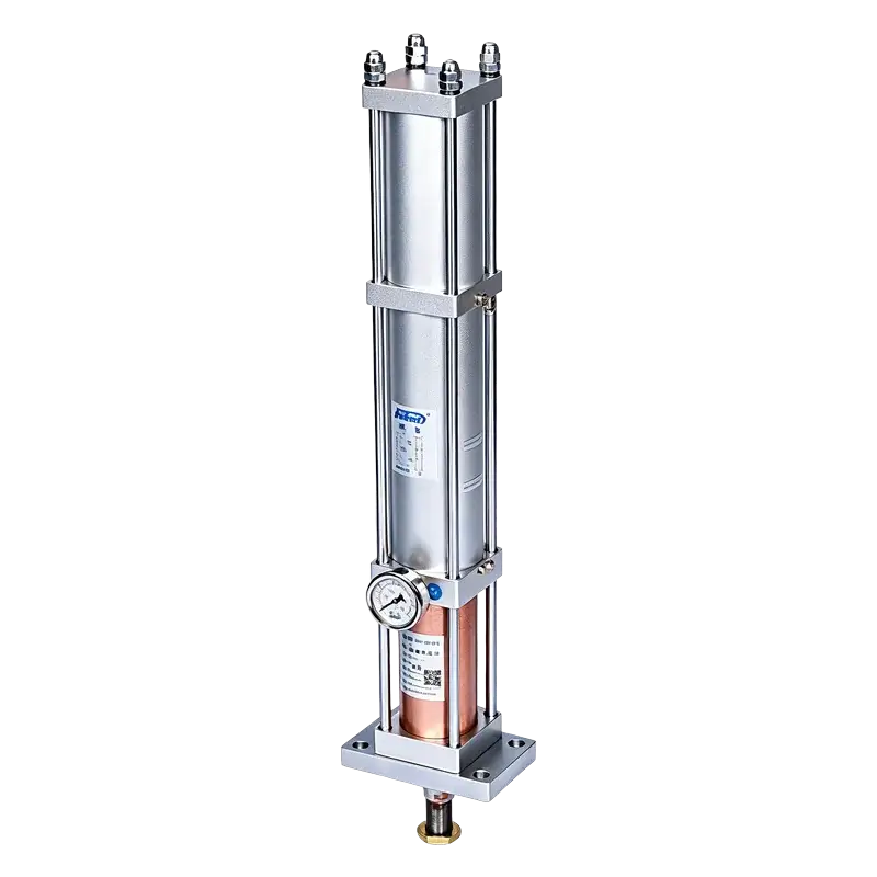
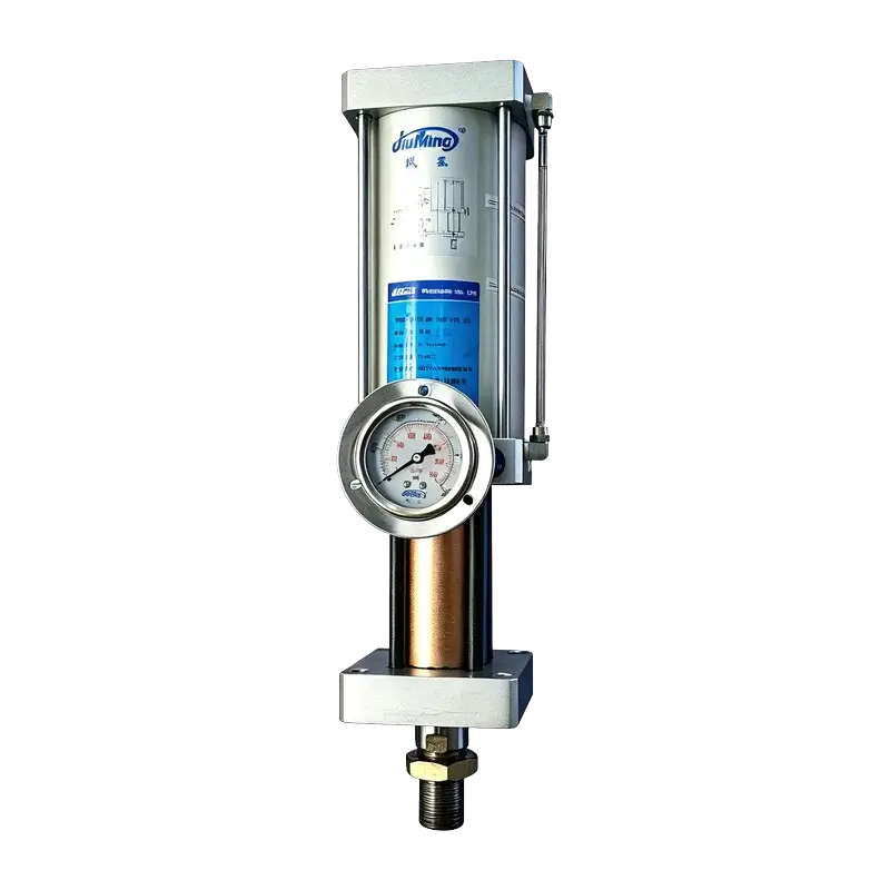
JRF Fast Single-Column Hydro-Pneumatic Booster Cylinder
Slim one-piece column design delivering 1-40 tons with 250-500 mm/s approach speed — the fastest approach in the JiuRong lineup for extrusion, bending, and heavy forming.
Why Fast Single-Column?
The JRF combines a slim one-piece column body with the fastest approach speed in the range and output up to 40 tons — ideal when space is tight but force demand is high.
External Oil Tank
Proven two-stage with separate reservoir; larger footprint, up to 40T.
Compact Integrated
Compact body, high cycling rate, but limited to 14T output.
JRF Fast Single-Column
Slim column body, 250-500 mm/s approach, up to 40T output.
Fastest Approach Speed
250-500 mm/s rapid approach — the fastest in the JiuRong HPC range, minimizing non-pressing cycle time.
Slim Single-Column Body
One-piece integrated column design with a small footprint and clean appearance, easy to integrate into tight machine layouts.
Up to 40 Tons
Widest force range in the lineup — 1-40T across 7 bore sizes from Φ63 to Φ160mm, covering light to heavy applications.
Stable High Force
Hydraulic intensification delivers consistent output with ±0.20mm power-stroke repeatability.
Simple & Maintainable
Fewer external components than standard pre-press types; standard VG68 oil and accessible internals reduce maintenance.
Wide Configurability
7 bore sizes, 3-5 tonnage options per bore, total strokes 50-400mm, and power strokes 5-20mm.
Technical Specifications
| Actuation Type | Double-Acting |
| High Pressure Output | 1-40 tons |
| Standard Tonnages | 5T / 10T / 20T / 30T / 40T |
| Operating Pressure | 4-7 kgf/cm² |
| Operating Frequency | 25-45 cycles/min |
| Operating Speed | 250-500 mm/s |
| Hydraulic Medium | VG68 Anti-Wear Oil |
| Operating Temperature | 0-60°C |
| Hyd. Cylinder Proof Pressure | 120 kgf/cm² |
| Air Cylinder Proof Pressure | 30 kgf/cm² |
| Pre-press Stroke Tolerance | +1.00 / 0.00 mm |
| Power Stroke Tolerance | +0.20 / 0.00 mm |
| Bore Sizes | Φ63 / 83 / 80 / 100 / 125 / 150 / 160 mm |
| Total Stroke Range | 50-400 mm |
| Power Stroke Options | 5 / 10 / 15 / 20 mm |
| Mounting | Vertical (standard) |
| Solenoid Valves | DT1 + DT2 (2 valves) |
| Certification | ISO 9001:2015 |
Force vs. Displacement Profile
The JRF rapid-approach phase reaches 250-500 mm/s, then switches to high-pressure boost for the final 5-20mm — fast approach plus full pressing force in a single slim unit.
The single-column body integrates both phases. The approach stroke is the fastest in the range; the boost stroke delivers up to 40 tons through 5-20mm.
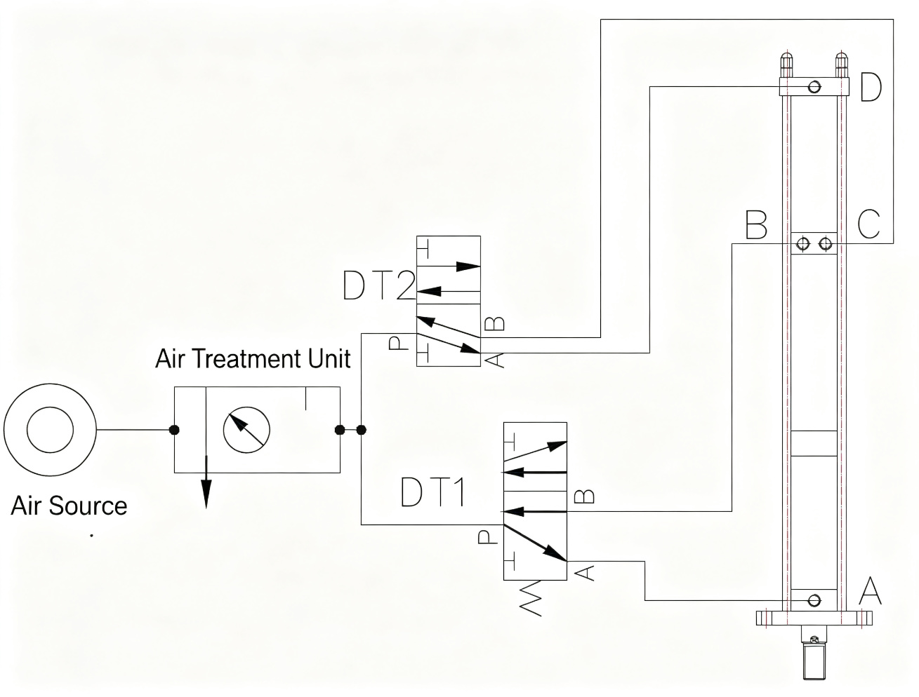
Pneumatic Circuit Diagram
Dual solenoid valves independently control the rapid approach and boost phases.
Operation Sequence (4-Step Cycle)
Two solenoid valves coordinate the rapid approach and high-force boost in a fully automatic cycle.
Rapid Approach
DT1 energizes. Air pressure acts on the hydraulic oil surface, driving the piston downward at high speed through the total stroke.
DT1 ON DT2 OFFBoost Stroke
The piston meets resistance. DT1 holds while DT2 energizes, activating the booster assembly for high-pressure output through the power stroke.
DT1 ON DT2 ONPressure Release
After the required dwell/holding time, DT2 de-energizes. The booster assembly retracts and the cylinder releases pressure.
DT1 ON DT2 OFFReturn Stroke
DT1 de-energizes. The cylinder assembly retracts, hydraulic oil flows back to the reservoir, and one cycle is complete.
DT1 OFF DT2 OFFMounting Configurations
Vertical (Standard)
Rod-down mounting on a press frame or machine platen. The standard configuration for all JRF models.
StandardCustom Orientation
Special mounting angles or configurations available on request. Contact our engineering team for non-standard layouts.
On RequestCustom Stroke & Force
Beyond the standard range, custom tonnages up to 40T and strokes up to 400mm can be engineered to order.
Up to 40TInstallation Dimensions
Select a bore size to view standard dimensions. All values in millimeters.
| Ton | A | B | C | D | E | F (Air Port) | G (Rear Port) | H | I | J | K | L | M (Rod Thread) | O | P |
|---|---|---|---|---|---|---|---|---|---|---|---|---|---|---|---|
| 5T | 80 | 100 | 132 | 65 | 14 | ZG3/8" | ZG3/8" | 117 | 50 | 35 | 50 | 22 | M16×1.5 | 67 | 95 |
| 10T | 90 | 100 | 132 | 65 | 14 | ZG3/8" | ZG3/8" | 117 | 50 | 35 | 50 | 22 | M16×1.5 | 67 | 95 |
| 20T | 91 | 120 | 155 | 65 | 17 | ZG1/2" | ZG1/2" | 125 | 50 | 38 | 60 | 25 | M20×1.5 | 78 | 110 |
| Ton | N @ 5mm Stroke | N @ 10mm Stroke | N @ 15mm Stroke | N @ 20mm Stroke |
|---|---|---|---|---|
| 5T | 530 | 587 | 643 | 700 |
| 10T | 530 | 587 | 643 | 700 |
| 20T | 615 | 686 | 755 | 825 |
| Ton | A | B | C | D | E | F (Air Port) | G (Rear Port) | H | I | J | K | L | M (Rod Thread) | O | P |
|---|---|---|---|---|---|---|---|---|---|---|---|---|---|---|---|
| 5T | 110 | 120 | 130 | 65 | 17 | ZG3/8" | ZG3/8" | 115 | 50 | 38 | 60 | 25 | M20×1.5 | 78 | 110 |
| 10T | 110 | 122 | 135 | 65 | 17 | ZG3/8" | ZG1/2" | 119 | 85 | 46 | 70 | 28 | M24×2 | 90 | 135 |
| 20T | 127 | 138 | 186 | 85 | 22 | ZG1/2" | ZG1/2" | 150 | 110 | 50 | 80 | 30 | M30×2 | 105 | 160 |
| Ton | N @ 5mm Stroke | N @ 10mm Stroke | N @ 15mm Stroke | N @ 20mm Stroke |
|---|---|---|---|---|
| 5T | 530 | 587 | 643 | 700 |
| 10T | 615 | 686 | 755 | 825 |
| 20T | 740 | 825 | 910 | 995 |
| Ton | A | B | C | D | E | F (Air Port) | G (Rear Port) | H | I | J | K | L | M (Rod Thread) | O | P |
|---|---|---|---|---|---|---|---|---|---|---|---|---|---|---|---|
| 5T | 91 | 120 | 155 | 65 | 17 | ZG3/8" | ZG1/2" | 125 | 50 | 38 | 60 | 25 | M20×1.5 | 90 | 135 |
| 10T | 110 | 138 | 186 | 85 | 22 | ZG1/2" | ZG1/2" | 150 | 85 | 50 | 80 | 30 | M24×2 | 105 | 160 |
| 20T | 126 | 150 | 190 | 85 | 22 | ZG1/2" | ZG3/4" | 160 | 110 | 58 | 90 | 35 | M30×2 | 120 | 180 |
| Ton | N @ 5mm Stroke | N @ 10mm Stroke | N @ 15mm Stroke | N @ 20mm Stroke |
|---|---|---|---|---|
| 5T | 587 | 643 | 700 | 756 |
| 10T | 715 | 795 | 875 | 955 |
| 20T | 800 | 890 | 980 | 1070 |
| Ton | A | B | C | D | E | F (Air Port) | G (Rear Port) | H | I | J | K | L | M (Rod Thread) | O | P |
|---|---|---|---|---|---|---|---|---|---|---|---|---|---|---|---|
| 10T | 126 | 150 | 190 | 85 | 22 | ZG1/2" | ZG3/4" | 160 | 110 | 58 | 90 | 35 | M30×2 | 120 | 180 |
| 20T | 150 | 180 | 250 | 100 | 26 | ZG3/4" | ZG3/4" | 195 | 130 | 65 | 110 | 40 | M36×2 | 145 | 220 |
| 30T | 170 | 200 | 260 | 120 | 30 | ZG3/4" | ZG1" | 210 | 160 | 75 | 130 | 45 | M42×2 | 165 | 250 |
| Ton | N @ 5mm Stroke | N @ 10mm Stroke | N @ 15mm Stroke | N @ 20mm Stroke |
|---|---|---|---|---|
| 10T | 800 | 890 | 980 | 1070 |
| 20T | 940 | 1045 | 1150 | 1255 |
| 30T | 1080 | 1200 | 1320 | 1440 |
| Ton | A | B | C | D | E | F (Air Port) | G (Rear Port) | H | I | J | K | L | M (Rod Thread) | O | P |
|---|---|---|---|---|---|---|---|---|---|---|---|---|---|---|---|
| 10T | 170 | 200 | 260 | 120 | 30 | ZG3/4" | ZG1" | 210 | 160 | 75 | 130 | 45 | M42×2 | 165 | 250 |
| 20T | 200 | 240 | 320 | 140 | 34 | ZG1" | ZG1 1/4" | 260 | 200 | 90 | 160 | 55 | M48×2 | 195 | 300 |
| 30T | 220 | 265 | 340 | 160 | 38 | ZG1" | ZG1 1/4" | 280 | 230 | 105 | 185 | 60 | M56×2 | 225 | 350 |
| Ton | N @ 5mm Stroke | N @ 10mm Stroke | N @ 15mm Stroke | N @ 20mm Stroke |
|---|---|---|---|---|
| 10T | 1080 | 1200 | 1320 | 1440 |
| 20T | 1280 | 1425 | 1570 | 1715 |
| 30T | 1480 | 1650 | 1820 | 1990 |
| Ton | A | B | C | D | E | F (Air Port) | G (Rear Port) | H | I | J | K | L | M (Rod Thread) | O | P |
|---|---|---|---|---|---|---|---|---|---|---|---|---|---|---|---|
| 20T | 200 | 240 | 320 | 140 | 34 | ZG1" | ZG1 1/4" | 260 | 200 | 90 | 160 | 55 | M48×2 | 195 | 300 |
| 30T | 230 | 280 | 380 | 160 | 38 | ZG1" | ZG1 1/4" | 310 | 240 | 105 | 190 | 60 | M56×2 | 230 | 360 |
| 40T | 260 | 320 | 420 | 180 | 42 | ZG1 1/4" | ZG1 1/2" | 340 | 280 | 120 | 220 | 70 | M64×2 | 260 | 420 |
| Ton | N @ 5mm Stroke | N @ 10mm Stroke | N @ 15mm Stroke | N @ 20mm Stroke |
|---|---|---|---|---|
| 20T | 1280 | 1425 | 1570 | 1715 |
| 30T | 1520 | 1695 | 1870 | 2045 |
| 40T | 1760 | 1965 | 2170 | 2375 |
| Ton | A | B | C | D | E | F (Air Port) | G (Rear Port) | H | I | J | K | L | M (Rod Thread) | O | P |
|---|---|---|---|---|---|---|---|---|---|---|---|---|---|---|---|
| 20T | 260 | 320 | 420 | 180 | 42 | ZG1 1/4" | ZG1 1/2" | 340 | 280 | 120 | 220 | 70 | M64×2 | 260 | 420 |
| 30T | 290 | 360 | 480 | 200 | 46 | ZG1 1/4" | ZG1 1/2" | 390 | 320 | 135 | 260 | 80 | M72×3 | 300 | 490 |
| 40T | 330 | 400 | 520 | 220 | 50 | ZG1 1/2" | ZG2" | 430 | 380 | 150 | 300 | 90 | M80×3 | 345 | 560 |
| Ton | N @ 5mm Stroke | N @ 10mm Stroke | N @ 15mm Stroke | N @ 20mm Stroke |
|---|---|---|---|---|
| 20T | 1760 | 1965 | 2170 | 2375 |
| 30T | 2050 | 2295 | 2540 | 2785 |
| 40T | 2380 | 2665 | 2950 | 3235 |
N values are calculated at 10mm power stroke. For strokes exceeding 10mm, refer to the engineering drawing. S = total stroke. Standard data; custom dimensions available on request.
Theoretical Output Force
Output force at 4-7 kgf/cm² supply pressure. Values in kgf.
| Bore | Model | 4 kgf/cm² | 5 kgf/cm² | 6 kgf/cm² | 7 kgf/cm² |
|---|---|---|---|---|---|
| 63mm | 5T | 1,800 | 2,250 | 2,700 | 3,150 |
| 63mm | 10T | 3,600 | 4,500 | 5,400 | 6,300 |
| 63mm | 20T | 7,200 | 9,000 | 10,800 | 12,600 |
| 83mm | 5T | 2,490 | 3,112 | 3,735 | 4,357 |
| 83mm | 10T | 4,980 | 6,225 | 7,470 | 8,715 |
| 83mm | 20T | 9,960 | 12,450 | 14,940 | 17,430 |
| 80mm | 5T | 2,880 | 3,600 | 4,320 | 5,040 |
| 80mm | 10T | 5,760 | 7,200 | 8,640 | 10,080 |
| 80mm | 20T | 11,520 | 14,400 | 17,280 | 20,160 |
| 100mm | 10T | 7,500 | 9,375 | 11,250 | 13,125 |
| 100mm | 20T | 15,000 | 18,750 | 22,500 | 26,250 |
| 100mm | 30T | 22,500 | 28,125 | 33,750 | 39,375 |
| 125mm | 10T | 9,375 | 11,719 | 14,063 | 16,406 |
| 125mm | 20T | 18,750 | 23,438 | 28,125 | 32,813 |
| 125mm | 30T | 28,125 | 35,156 | 42,188 | 49,219 |
| 150mm | 20T | 18,000 | 22,500 | 27,000 | 31,500 |
| 150mm | 30T | 27,000 | 33,750 | 40,500 | 47,250 |
| 150mm | 40T | 36,000 | 45,000 | 54,000 | 63,000 |
| 160mm | 20T | 20,480 | 25,600 | 30,720 | 35,840 |
| 160mm | 30T | 30,720 | 38,400 | 46,080 | 53,760 |
| 160mm | 40T | 40,960 | 51,200 | 61,440 | 71,680 |
Above data are theoretical values. Actual output force is recommended not to exceed 50% of the theoretical value to avoid affecting operating speed.
JRF vs JRA vs JRG
Choose the right two-stage architecture for your application.
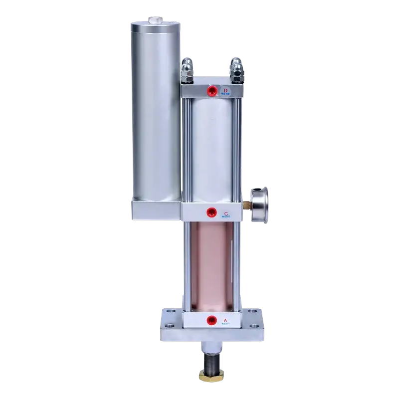
JRA Standard
Classic two-stage design with external oil reservoir. Proven for general pressing up to 40T.
- General pressing & forming
- Horizontal mounting needs
- Wide force range
JRG Composite
Integrated two-stage design with highest cycling rate, but limited to 14T output.
- High-cycle automation
- Space-constrained installs
- Plastic welding & riveting
JRF Fast Single-Column
Slim one-piece column with the fastest approach speed and output up to 40T.
- Extrusion & bending
- Heavy forming & punching
- Tight machine layouts
Build Your Model Number
Select parameters to generate your JRF model code and see theoretical output force in real time.
Need a custom configuration? Send us your model code →
Selection Guide
Specify these seven parameters when requesting a quotation.
Typical Applications
Extrusion
Metal and plastic extrusion forming
Bending
Sheet metal and profile bending
Hole Punching
High-force punching and piercing
Forming & Riveting
Heavy forming, riveting and staking
Assembly
Press-fit and insertion operations
Marking & Embossing
Part marking and logo embossing
Resources & Downloads
Ready to Configure Your JRF?
Send us your requirements and our engineering team will recommend the exact model for your application.