What is a Hydro-Penumatic-Booster-Cylinder
A pneumatic cylinder is simple, fast, and easy to control, but the force it can produce is fundamentally limited by available air pressure and piston area. A hydraulic cylinder can generate much higher force, but it normally belongs to a hydraulic system that must supply and control pressurized oil.
A hydro-pneumatic booster cylinder sits between these two approaches.
It uses compressed air as its external power source, but introduces a hydraulic pressure-intensification stage inside the actuator. The result is an actuator designed to retain much of the operating simplicity of pneumatics while producing a much higher working force through hydraulic pressure.
That combination is the key to understanding the product. A hydro-pneumatic booster cylinder is not simply an air cylinder with more force, and it is not simply a hydraulic cylinder driven in a different way. Its structure and motion sequence are designed around a different engineering idea: use pneumatic energy for motion and control, then use hydraulic intensification when substantial working force is required.
JiuRong's general product material describes the architecture as an integrated combination of a pneumatic and hydraulic section, using compressed air as the power source and piston-area ratio together with Pascal's principle to raise the pressure delivered to the hydraulic working section.
What Is a Hydro-Pneumatic Booster Cylinder?
At the simplest level, a hydro-pneumatic booster cylinder converts relatively low pneumatic pressure into substantially higher hydraulic pressure.
Compressed air does not directly produce the final pressing force in the same way that it does in a conventional pneumatic cylinder. Instead, air acts on the pneumatic and intensifier sections of the actuator. The intensifier then acts on hydraulic oil, and the resulting hydraulic pressure drives the working piston and output rod.
Conceptually, the energy path can be understood as:
Compressed air → pneumatic force → hydraulic pressure intensification → hydraulic piston force → linear output
This distinction matters.
A conventional pneumatic cylinder generates output approximately from the relationship between air pressure and piston area. Increasing force therefore normally means increasing air pressure, piston diameter, or both.
A hydro-pneumatic booster cylinder introduces another stage between the air supply and the final working piston. A relatively large pneumatic piston can drive a much smaller intensifier plunger. The same driving force is therefore concentrated onto a smaller hydraulic area, producing a higher oil pressure.
Ignoring mechanical and hydraulic losses for explanation purposes:
Pneumatic force ≈ air pressure × pneumatic piston area
The intensifier then converts that force into hydraulic pressure according to the effective area ratio, and the hydraulic pressure acts on the output piston:
Output force ≈ intensified hydraulic pressure × hydraulic piston area
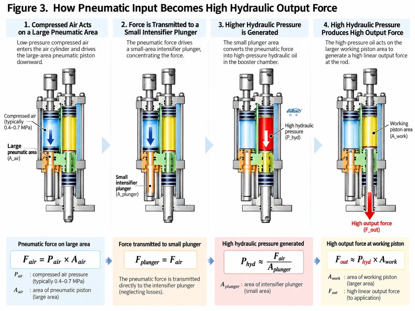
This is why the final output cannot be understood from air pressure alone. It depends on the complete relationship between supply pressure, intensifier geometry and hydraulic output area.
The manufacturer's general technical material likewise defines the operating principle around the cross-sectional area ratio of the large and small intensifier pistons and the transmission of the resulting pressure to the hydraulic cylinder.
Inside the Cylinder: Structure Follows Function
Although different booster-cylinder designs arrange their components differently, the important structure is easier to understand by looking at function rather than by memorizing individual parts.
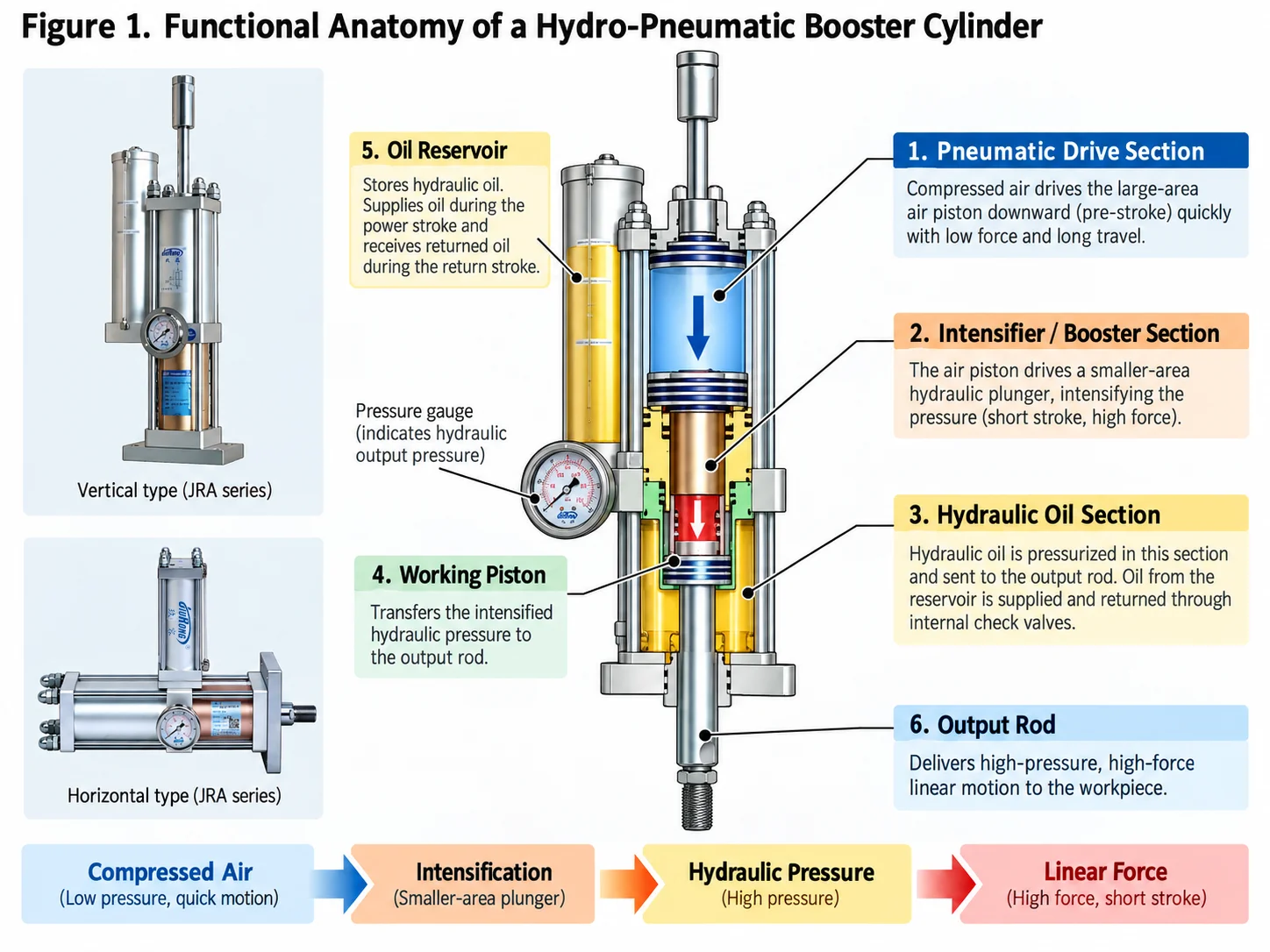
The first functional section is the pneumatic drive section. It receives compressed air and provides the motion that initiates the actuator cycle and drives the intensification mechanism.
The second is the hydraulic working section. Hydraulic oil transmits pressure to the working piston and output rod. Because hydraulic oil is far less compressible than air, it provides a stiffer pressure-transmission medium during the force stage. The higher output force itself comes from hydraulic pressure intensification acting on the working piston area.
Between the two sits the defining element of the product: the intensifier. Its unequal effective piston areas convert pneumatic input into higher hydraulic pressure.
An oil reservoir or oil-storage section maintains the hydraulic medium required by the working circuit, while seals separate pneumatic and hydraulic sections and control leakage between the two media.
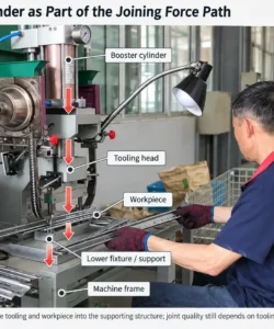
The piston rod is the mechanical output element. It transfers the generated linear force to the tooling, fixture or workpiece.
This arrangement explains why describing a booster cylinder merely as a "combination of air and oil" is incomplete. The two media have different jobs:
air provides the external energy and control medium; hydraulic oil carries the intensified pressure to the force-producing output stage.
They are not simply mixed together.
The Most Important Concept: Travel and Force Do Not Always Occur in the Same Stage
A typical pre-stroke hydro-pneumatic booster cylinder does not need maximum force throughout its entire travel.
This is one of the most important differences to understand.
Consider a press operation. The tool may need to travel a significant distance from its home position before it reaches the workpiece. Very little force is required during most of that movement. High force is needed only after contact, during pressing, forming, riveting or assembly.
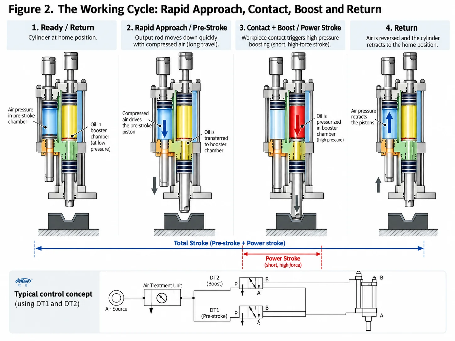
A typical pre-stroke booster cylinder therefore separates the cycle into functional phases.
Rapid Approach or Pre-Stroke
The piston rod travels toward the workpiece before the high-pressure intensification phase begins.
In the general JiuRong operating sequence, compressed air first drives the pre-pressure section so that hydraulic oil moves the working piston toward the workpiece while the booster piston remains retracted.
This phase is primarily about travel, not maximum pressing force.
Workpiece Contact
The output rod reaches the tooling or workpiece.
At this point, the actuator no longer needs long free movement. The process now requires force.
Pressure Intensification
Compressed air is applied to the booster piston. The intensifier acts on the hydraulic oil in the working chamber, raising its pressure.
The hydraulic working piston then converts that pressure into the high output force required by the process.
Power Stroke
The short portion of travel performed under intensified hydraulic pressure is commonly called the power stroke, boost stroke or high-pressure stroke.
This distinction is visible directly in the JRA standard-series model structure. JRA defines total stroke and power stroke separately—for example, its model coding can specify a 100 mm total stroke together with a 10 mm power stroke.
That does not mean only 10 mm of the cylinder can move. It means the complete actuator travel and the high-force portion of that travel are different engineering variables.
This is why a booster cylinder can be particularly useful in machinery where the actuator must:
- move quickly over a larger distance,
- contact the workpiece, and
- then apply much higher force over a comparatively short working distance.
Return
After the pressing operation or required holding period is complete, the intensifier returns and the working piston retracts to its initial position.
The next cycle can then begin.
Not Every Hydro-Pneumatic Booster Cylinder Uses a Separate Pre-Stroke
The two-stage explanation above describes an important and common booster-cylinder architecture, but it should not be treated as a universal rule for every design.
Direct-acting booster cylinders provide an important counterexample.
JiuRong's JRE direct-acting series does not have a separate total-stroke section followed by an independent power stroke. Its total stroke is effectively the pressure stroke.
The supplied material describes this architecture as full-stroke high-pressure operation with motion similar to a pneumatic cylinder, and identifies applications such as marking, bearing assembly, electronic-component riveting and sheet-metal forming.
This distinction is useful because it shows that hydro-pneumatic booster cylinder describes an operating principle, not one fixed mechanical layout.
The essential concept is pneumatic-to-hydraulic intensification. How the designer arranges travel, pressure stroke, oil reservoir, mounting direction and control sequence can vary according to the machine requirement.
Why Use a Booster Cylinder Instead of a Pneumatic Cylinder?
A pneumatic cylinder uses compressed air directly against a piston.
That architecture is attractive because it is simple, fast and easy to integrate into automated equipment. But when pressing force rises, the required pneumatic piston diameter can become large because plant-air pressure is relatively limited.
A booster cylinder addresses this by adding hydraulic intensification rather than relying only on a larger pneumatic piston.
The result is not that the booster cylinder "replaces pneumatics." It still depends on compressed air. The difference is that pneumatic energy is used more strategically.
A conventional pneumatic actuator is a natural choice when the process mainly requires:
light to moderate force, straightforward motion, rapid cycling and simple pneumatic control.
A hydro-pneumatic booster cylinder becomes more relevant when the same machine also needs a substantially higher pressing force than a practical direct pneumatic actuator can provide.
That is the first useful engineering boundary:
Choose the architecture according to the force profile of the process, not simply according to whether compressed air is available.
Why Use a Booster Cylinder Instead of a Conventional Hydraulic Cylinder?
A hydraulic cylinder already converts fluid pressure into high linear force, so at first glance a booster cylinder can appear redundant.
The difference lies in how that hydraulic pressure is created and how much of the machine actually needs hydraulic power.
A conventional hydraulic actuator normally depends on an external hydraulic pressure source and the surrounding hydraulic circuit required by the machine design.
A hydro-pneumatic booster cylinder uses compressed air as its external power input and creates the required high hydraulic pressure locally through the intensifier.
That can be attractive when a machine already has a pneumatic infrastructure and requires high force mainly during a limited part of its cycle.
The manufacturer's general materials position the hydro-pneumatic combination around fast motion, high output force, pneumatic-style control and relatively straightforward installation and maintenance.
That does not mean a booster cylinder is universally superior to hydraulics.
If the process requires long high-force travel, continuous hydraulic force over most of the motion profile, large hydraulic flow, or functions that naturally belong to a broader hydraulic system, a conventional hydraulic architecture may be the more natural engineering solution.
The booster cylinder is most distinctive where high force is concentrated into a limited working portion of the machine cycle.
Pneumatic, Hydro-Pneumatic and Hydraulic Actuation in Context
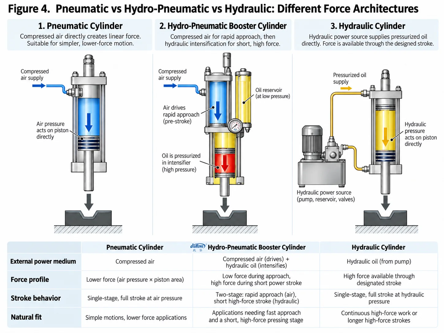
| Engineering characteristic | Pneumatic cylinder | Hydro-pneumatic booster cylinder | Hydraulic cylinder |
|---|---|---|---|
| Primary energy / actuation | Compressed air | Compressed air + internal hydraulic intensification | Hydraulic pressure |
| Force capability | Limited by air pressure and piston area | High force concentrated in power stroke or boosted phase | High force available hydraulically |
| Motion speed | Usually fast | Fast approach possible + high-force working phase | Depends on hydraulic flow/system design |
| Force behavior | Air compressibility affects stiffness | Hydraulic medium used during force stage | Hydraulic medium throughout actuation |
| System requirement | Pneumatic supply and valves | Pneumatic supply + integrated pneumatic-hydraulic mechanism | Hydraulic power unit, reservoir, valves, piping |
| Best-fit logic | Light/medium force, high simplicity | Fast approach + short high-force work | Sustained/full-stroke hydraulic force and broader hydraulic motion control |
The purpose of this comparison is not to select a universal winner. It is to expose the different force and motion architectures.
A booster cylinder makes sense because some industrial processes do not require the same force during every millimeter of actuator travel.
What This Architecture Does Well
Once the internal principle is understood, the product characteristics can be summarized more usefully as consequences of the architecture rather than as a separate list of promotional advantages.
- High force through hydraulic intensification: the force increase comes from raising hydraulic pressure rather than treating plant air pressure itself as the final working pressure.
- Fast approach with a short high-force working phase: in typical pre-stroke designs, the actuator can approach the workpiece before entering the boosted power stroke.
- Pneumatic-compatible actuation and control: compressed air remains the external power source, which can suit machines already designed around pneumatic utilities and controls.
- Integrated pneumatic-hydraulic force conversion: the booster-cylinder architecture combines pneumatic drive and hydraulic intensification within one actuator system, allowing a local high-force stage in appropriate machine designs.
- Hydraulic pressure transmission during the boosted stage: the working piston receives intensified hydraulic pressure during the force-producing phase rather than relying only on compressed air acting directly on the final output piston.
These characteristics should always be read in context. They describe why the technology exists; they do not mean every booster-cylinder design has the same stroke, force, cycle rate, mounting direction or operating limits.
Where Hydro-Pneumatic Booster Cylinders Are Used
The most useful way to understand applications is not to memorize industries. It is to look for a common process requirement.
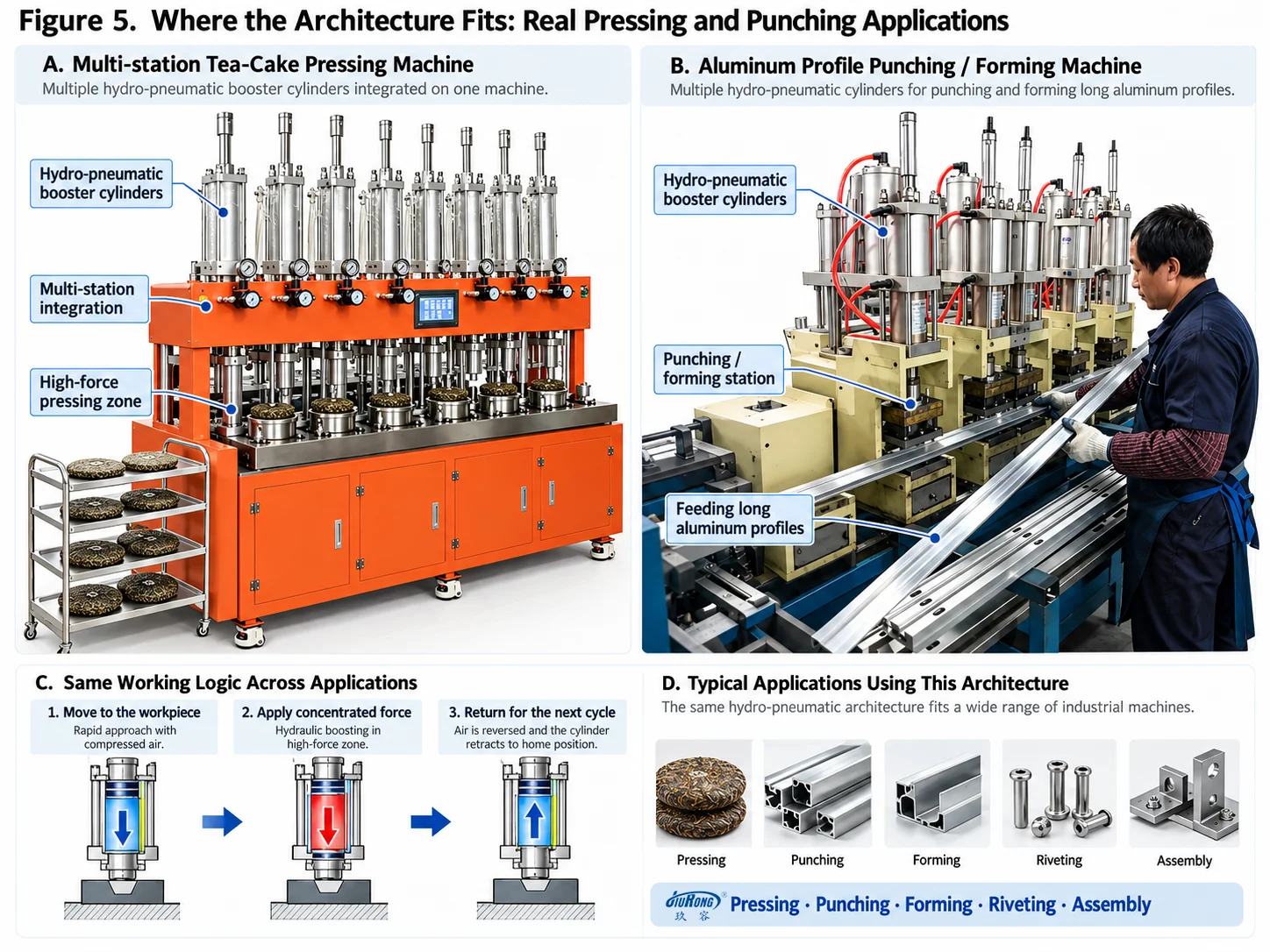
Hydro-pneumatic booster cylinders are particularly relevant where a machine needs controlled linear movement followed by substantial working force.
The JRA standard-series material identifies operations including extrusion, bending, punching, forming, riveting, deburring, assembly and marking.
These processes can be grouped by what the actuator actually does.
Press fitting and assembly
Press fitting and assembly involve pushing one component into or against another, such as bearing, bushing or hardware assembly.
Riveting and clinching
Riveting and clinching need concentrated force to permanently deform or join components.
Forming and bending
Forming and bending require force to change the geometry of a metal or other workpiece through tooling.
Punching / stamping-type operations
Punching and related press operations require a short, force-intensive working event after tooling has reached the workpiece.
Marking and pressing
Marking and pressing operations may require relatively short travel but more force than a practical direct pneumatic actuator provides.
Plastic joining / welding-related pressing
Certain hydro-pneumatic booster-cylinder configurations are also used in plastic joining or welding-related pressing processes where controlled motion is followed by a force-intensive working stage.
The common thread is not the industry label. It is the force-versus-stroke profile.
That profile should be understood before choosing actuator architecture.
Practical Operating Considerations
A booster cylinder should not be selected from output tonnage alone.
The machine designer must also consider total travel, required high-force travel, available compressed-air pressure, return requirements, operating frequency, mounting orientation and the relationship between the cylinder and tooling.
For the JiuRong product family covered by the supplied material, compressed air is the stated power source. The general documentation specifies 0.4–0.7 MPa supply pressure and identifies 0.6 MPa as the company's standard pressure for output calculations. It also specifies ISO VG68 anti-wear hydraulic oil and recommends a stable air supply; where air availability may fluctuate, an air reservoir ahead of the air-preparation unit is recommended. These are manufacturer-specific operating references rather than universal specifications for every hydro-pneumatic booster cylinder.
Mounting also matters. Different architectures are designed for different orientations, and a cylinder intended for one orientation should not automatically be assumed suitable for another. Horizontal, inverted and separated configurations exist precisely because mechanical layout and oil management affect the design.
This is another reason not to reduce booster-cylinder selection to "required tons."
The actuator must fit the whole motion and force requirement of the machine.
The Engineering Idea Behind the Product
A hydro-pneumatic booster cylinder is easiest to understand when it is viewed not as a hybrid label, but as a deliberate division of work between two media.
Compressed air is convenient for machine actuation and control.
Hydraulic oil is effective for transmitting high pressure to a working piston.
The intensifier connects those two functions.
In a typical pre-stroke design, the cylinder uses relatively low-force movement to approach the workpiece and reserves intensified hydraulic pressure for the shorter phase where the process actually needs substantial force. Other designs, such as direct-acting booster cylinders, adapt the same pneumatic-to-hydraulic principle to a full high-pressure stroke.
That is the central engineering value of the product:
it allows the machine designer to use pneumatic power and control while introducing hydraulic force where the process requires it, without treating every part of the actuator cycle as the same force problem.
That is also the best way to decide whether a hydro-pneumatic booster cylinder belongs in a machine. The starting question is not "How many tons can it produce?"
It is:
How much travel does the process need, where in that travel is high force actually required, and what actuator architecture delivers that force profile most naturally?
 Two Pressing Points, One Setup? What a Dual-Head Riveting Station Must Get Right
 How to Choose a Cost-Effective Actuator for a Riveting Press
 Why a Booster Cylinder Fits the Punching Station of a Long Aluminum Profile Machine
 When Hydro-Pneumatic Booster Cylinders Fit Riveting, Clinching and Press-Fit Equipment
Leave a Reply