Diagnosing a 500 kgf Force Difference in a Hydro-Pneumatic Multi-Station Press
A five-station automated press can be supplied from the same pneumatic system, use the same type of hydro-pneumatic booster cylinder and run the same production sequence, yet still produce a meaningful force difference at one station.
In this case, four stations show similar pressing-force values while one station is approximately 400–600 kgf lower. Two visible readings, 3465 kgf and 2960 kgf, differ by 505 kgf.
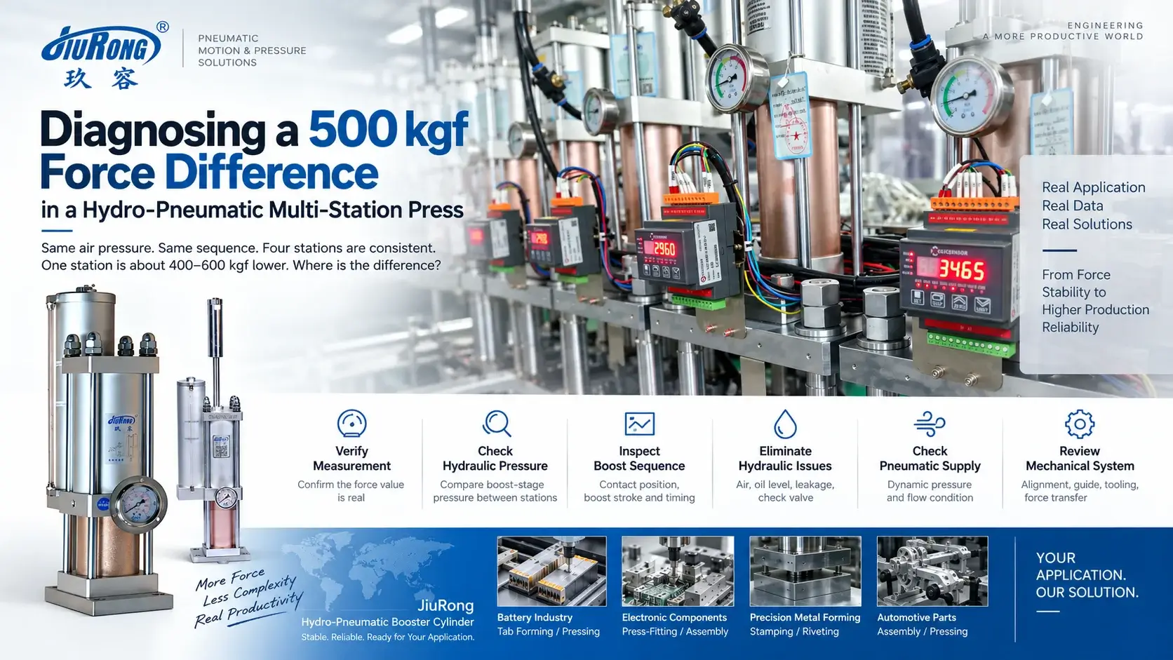
The immediate question is therefore not simply how to increase the pressure.
The useful question is:
At what point in the force-generation chain does the abnormal station begin to behave differently from the other four?
That changes the troubleshooting method completely.
Equal Air Pressure Does Not Prove Equal Pressing Force
A hydro-pneumatic booster cylinder does not use the pneumatic supply pressure directly as the final pressing pressure.
During the high-force stage, pneumatic energy drives an intensification process that generates hydraulic pressure. The working cylinder then converts that pressure into output force.
In simplified form:
F = Ph × A
where F is pressing force, Ph is high-pressure hydraulic pressure and A is the effective piston area.
For cylinders with the same effective area, a real difference in output force therefore has to come from somewhere in the complete chain:
Measurement --> pneumatic supply --> boost action --> hydraulic pressure --> working cylinder --> machine structure --> tooling --> force sensor
This is why comparing only the common air-pressure setting cannot identify the cause of a 500 kgf difference.
First Establish Whether the Force Difference Is Real
Because the displayed values are measured in kgf, the first check should be the force-measurement chain.
A low value can originate from the sensor, signal conditioner, display scaling, zero offset, wiring or the way the sensor is loaded mechanically. If the cylinder is dismantled before this is checked, a measurement problem can easily be mistaken for a hydraulic problem.
A practical cross-check is to exchange the measurement channel of the abnormal station with a known-good station where the machine design allows it.
If the low reading moves with the sensor or display channel, the fault follows the measurement system.
If the low reading remains at the same mechanical station, the force difference is much more likely to be generated within that station.
This is the fastest way to divide the problem before touching the booster cylinder.
Then Compare the High-Pressure Side, Not Only the Air Supply
Once the measurement system is confirmed, compare the actual high-pressure hydraulic condition of a normal station and the abnormal station during the boost stage.
This is the most important diagnostic split.
If the Abnormal Station Also Develops Lower Hydraulic Pressure
The investigation remains on the pressure-generation side. Possible areas include:
- Incomplete boost action
- Insufficient effective boost travel
- Air in the hydraulic circuit
- Insufficient oil volume
- Internal leakage
- Check-valve sealing
- Pneumatic valve or flow restriction
If Both Stations Develop Comparable Hydraulic Pressure but the Measured Force Is Still Different
Attention should move away from the intensifier and toward the machine.
Possible causes include:
- Additional guide friction
- Tooling misalignment
- Eccentric loading
- Different fixture height
- Incorrect force-sensor loading
The same symptom at the display can therefore come from two fundamentally different systems.
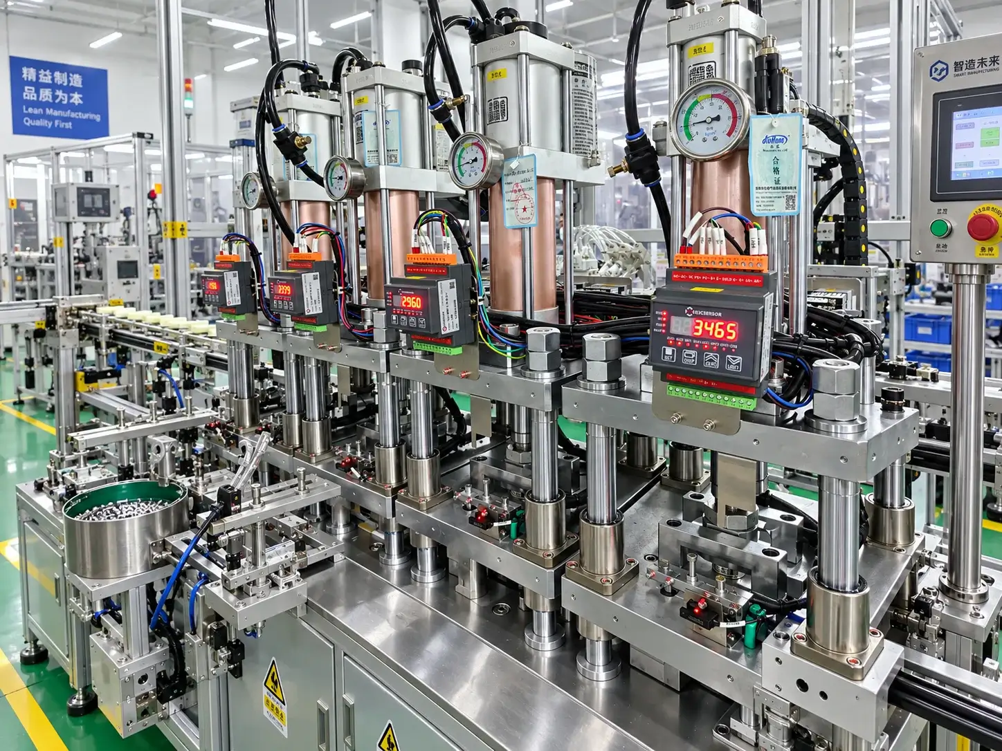
Check When the Boost Stage Actually Begins
One of the most easily overlooked causes in a multi-station press is a difference in the mechanical condition at the point where boosting begins.
A typical hydro-pneumatic press cycle can be considered as:
Rapid approach --> contact --> boost --> high-force pressing --> return
The controller may send the same command to all five stations, but the cylinders do not necessarily encounter the workpiece under exactly the same physical condition.
A small difference in:
- Tooling height
- Fixture position
- Workpiece stack height
- Contact position
- Sensor position
- Effective boost stroke
- Boost dwell time
can change how much of the intensification stage is available before the pressing operation reaches its end condition.
For that reason, compare the abnormal station with a normal station at four points:
- Position at first contact
- Position at boost initiation
- Force-rise time
- Peak-force hold condition
A PLC command being identical does not prove that the mechanical boost event is identical.
Use the Force Pattern to Narrow the Fault
The shape of the problem is often more useful than the force number alone.
If one station is consistently about 400–600 kgf lower on repeated cycles, look first for repeatable differences such as calibration, boost position, tooling geometry or a stable pressure restriction.
If the force varies significantly from cycle to cycle, investigate unstable conditions such as air in the hydraulic circuit, valve behavior, pneumatic-flow variation or intermittent mechanical resistance.
If force rises normally but falls during the hold period, internal hydraulic leakage or a sealing/check-valve issue becomes more relevant.
If force builds noticeably more slowly than the other four stations, inspect the conditions required to establish hydraulic pressure: oil condition, trapped air, pneumatic flow and boost sequencing.
The important point is that these signatures should not all be treated as the same “low pressure” fault.
Why Increasing the Regulator Is the Wrong First Correction
When one station reads 2960 kgf and another reads 3465 kgf, it is tempting to raise the pneumatic setting of the low station until the display approaches the others.
That can hide the actual fault.
If the measurement system is offset, the real force may already be correct.
If the hydraulic circuit contains air, increasing pressure does not remove the compressibility.
If an internal seal is leaking, more pressure may temporarily compensate for the loss without correcting it.
If the tooling is misaligned, additional force can increase side load and guide wear.
Pressure adjustment should therefore follow diagnosis, not replace it.
A Practical Service Sequence for the Five-Station Machine
For this type of after-sales case, the most efficient sequence is:
- Record several cycles from all five stations.
Determine whether the abnormal value is repeatable, unstable, slow to build or unable to hold. - Cross-check the force-measurement system.
Determine whether the low reading follows the sensor/display channel or remains with the machine station. - Compare boost-stage hydraulic pressure.
Establish whether the force difference already exists in the hydraulic intensification stage. - Compare contact and boost conditions.
Check contact position, boost initiation, effective boost travel, rise time and hold time. - Inspect the hydraulic side if pressure is low.
Check oil quantity, trapped air, leakage and relevant sealing/check-valve conditions. - Check dynamic pneumatic conditions.
Compare pressure and flow during the actual boost event rather than relying only on static manifold pressure. - Inspect the mechanical force path if hydraulic pressure is normal.
Check guides, tooling alignment, fixture height, eccentric load and force-sensor installation.
This sequence isolates the system before parts are replaced.
Stable High Force Is a System Condition
For an automated multi-station press, Stable High Force for Automated Assembly should not be interpreted as a pressure setting on the cylinder.
The force seen at the workpiece is the result of the complete system.
A useful after-sales diagnosis therefore follows the same path as the force itself:
Force reading --> hydraulic pressure --> boost sequence --> pneumatic supply --> cylinder condition → mechanical load path
In this five-station case, the 400–600 kgf difference provides a clear diagnostic signal. What it does not provide, by itself, is proof of a failed booster cylinder.
The correct service decision comes from identifying where the abnormal station first diverges from the other four.
 Two Pressing Points, One Setup? What a Dual-Head Riveting Station Must Get Right
 How to Choose a Cost-Effective Actuator for a Riveting Press
 Why a Booster Cylinder Fits the Punching Station of a Long Aluminum Profile Machine
 When Hydro-Pneumatic Booster Cylinders Fit Riveting, Clinching and Press-Fit Equipment
Leave a Reply