Why This Hydro-Pneumatic Forming Machine Uses Dual Air Receiver Tanks
A high-force forming machine is easy to evaluate only in terms of pressing force.
That can miss an equally important part of the machine architecture:
Can the pneumatic system deliver enough air, fast enough, when the machine cycle actually demands it?
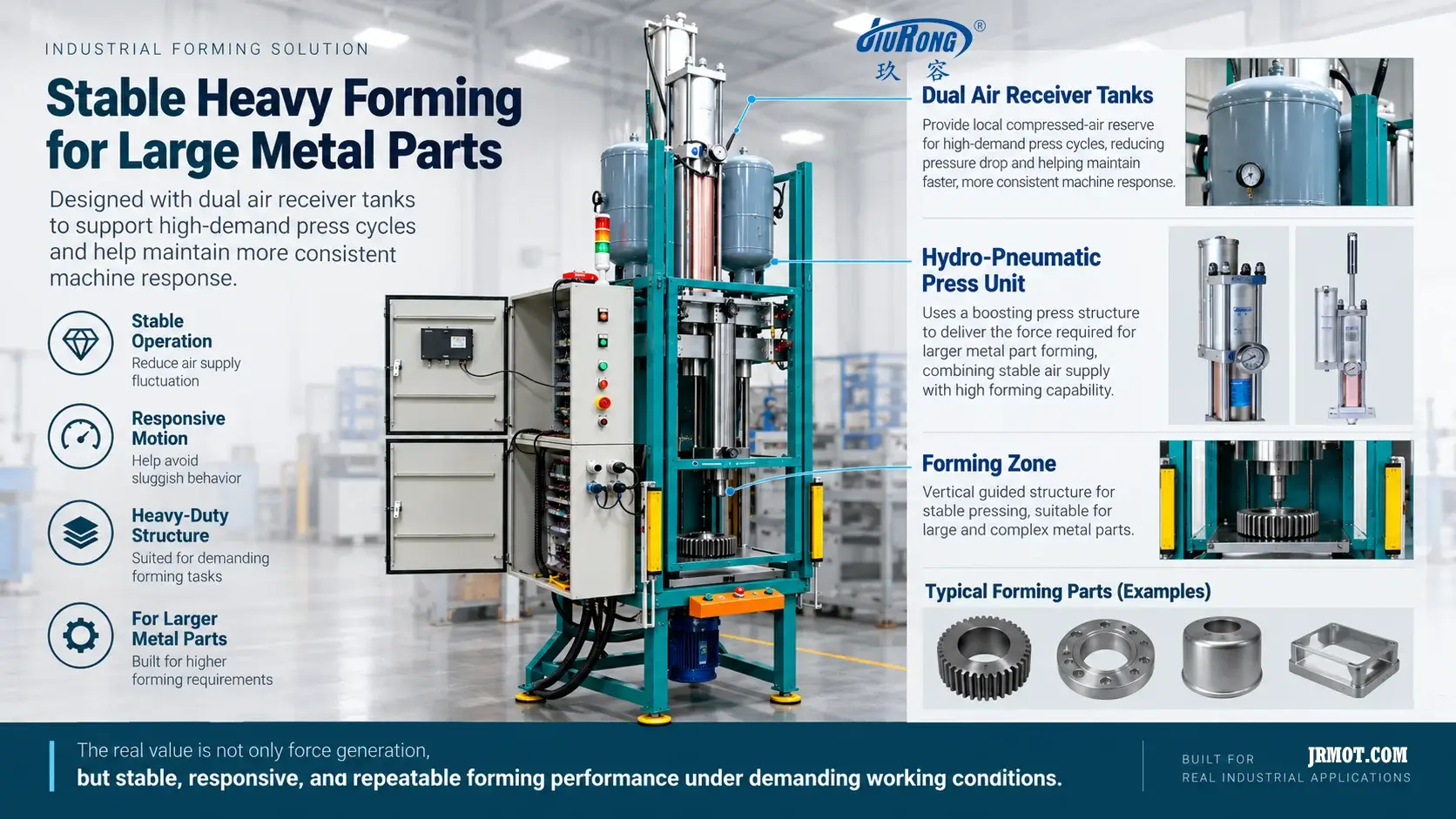
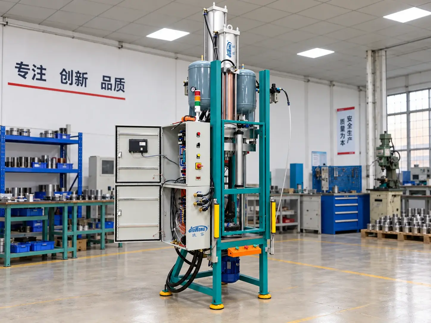
The machine shown here is built for forming relatively large metal parts. Its central hydro-pneumatic press unit provides the high-force working action, while two air receiver tanks are mounted close to the actuator system.
Those tanks are not there to create the forming force.
Their role is to support the air-delivery side of the machine.
High Force Is Only One Part of the System Problem
A hydro-pneumatic booster or press unit uses compressed air as part of its operating energy path.
That means machine behavior depends not only on actuator sizing, but also on whether sufficient compressed air is available during the cycle.
This distinction matters most during short periods of high demand.
A forming machine may have several pneumatic functions operating within a relatively short cycle:
- actuator approach and return;
- booster operation;
- valves and auxiliary pneumatic devices;
- clamping or supporting functions;
- repeated cycling before the upstream air system has fully recovered.
When these demands occur together, the machine may temporarily require more airflow than the plant-air network can deliver through the local piping and valves at that instant.
The result does not necessarily appear as a complete loss of pressure.
It may appear as something more subtle:
slower response, delayed motion, or a machine that begins to feel “dragging” during demanding cycles.
Why Nominal Air Pressure Is Not Enough
Compressed-air systems are often discussed mainly in terms of pressure.
But pressure at rest and air availability during a dynamic machine cycle are not the same thing.
A pressure gauge may show an acceptable supply pressure before the cycle begins. Once a large pneumatic volume starts consuming air, however, the local pressure can fall if the upstream system cannot replace that air quickly enough.
Several factors can contribute:
- long or undersized supply piping;
- restrictive fittings;
- insufficient valve flow capacity;
- pressure losses through air-treatment components;
- multiple machines consuming air simultaneously;
- high cycle frequency;
- limited upstream compressor or receiver recovery.
For the machine designer, the more useful question is therefore not only:
What is the available supply pressure?
It is also:
What airflow can actually reach the machine during the highest-demand part of the cycle?
What the Dual Receiver Tanks Actually Do
The two receiver tanks provide a local volume of stored compressed air close to the machine.
During lower-demand periods, the tanks can recharge from the plant-air network.
When the machine enters a high-demand portion of the cycle, that stored air is available locally rather than requiring the entire instantaneous flow to arrive through the upstream supply line at once.
Conceptually:
plant air → local storage → short high-demand machine event
The receiver therefore acts as a pneumatic buffer between the factory air network and the machine.
This can help reduce transient pressure drop and support more consistent pneumatic response during demanding operating periods.
The important point is not simply that the machine has “more air.”
It is that part of the required air volume is stored close to the point of use.
That changes the way the machine responds to short-duration airflow demand.
The Tanks Do Not Generate the Forming Force
It is important not to confuse air-storage capacity with actuator force.
The actual forming force is generated by the hydro-pneumatic press architecture.
The receiver tanks support the pneumatic energy supply to that system.
These are different engineering functions:
Air receiver tanks
→ provide local pneumatic reserve.
Hydro-pneumatic press unit
→ develops the required high-force working action.
Guided machine structure
→ carries and controls the forming load through the tooling and workpiece.
This distinction matters because a larger receiver tank does not automatically create a stronger press.
Likewise, installing a larger booster cylinder does not automatically solve an airflow limitation.
The machine has to be considered as a complete system.
Why the Machine Uses Two Tanks
The visible dual-tank arrangement suggests that local air-storage capacity is an important part of this machine's pneumatic architecture.
What cannot be determined from the image alone is the exact engineering reason for using two tanks instead of one of a different volume.
That decision could depend on factors such as:
- required stored air volume;
- packaging around the press structure;
- pneumatic circuit layout;
- symmetry or machine integration;
- replenishment behavior;
- component availability.
Without tank specifications and pneumatic circuit data, those possibilities should remain engineering considerations rather than claimed facts.
What the installation does make clear is that the machine designer has chosen to place substantial pneumatic storage directly beside the press system instead of relying only on remote factory air.
That is the more important system-level observation.
Why This Matters for Large-Part Forming
Forming larger or more complex metal parts can place several simultaneous demands on a machine:
- substantial working force;
- rigid guidance;
- stable tooling alignment;
- sufficient actuator travel;
- repeatable cycle response;
- adequate pneumatic energy delivery.
The visible machine architecture addresses these as separate but connected problems.
The vertical frame and guidance manage the mechanical load path.
The hydro-pneumatic press unit provides the high-force forming action.
The local receivers support the compressed-air supply during high-demand operation.
The engineering value therefore comes from the relationship:
air supply + local storage + actuator behavior + machine structure + forming load
rather than from any single component in isolation.
What Machine Builders Should Check
When a hydro-pneumatic machine shows slow or inconsistent response during demanding cycles, simply increasing nominal air pressure is not necessarily the first or only answer.
The pneumatic supply should be evaluated as a dynamic system.
1. Available pressure at the machine
Measure the actual pressure where the machine receives air, not only at the compressor room or main header.
More importantly, observe what happens to that pressure during the cycle.
2. Available airflow
Confirm that supply piping, fittings, regulators and valves can deliver the required flow.
A pressure source with insufficient flow capacity can still result in poor dynamic response.
3. Pressure drop during peak demand
The critical condition is often not steady-state operation but the short interval when several pneumatic volumes are filling or exhausting.
A meaningful diagnosis should therefore look for transient pressure sag during that part of the cycle.
4. Receiver capacity and location
Local receivers can be useful when short-duration machine demand is higher than the upstream network can comfortably supply instantaneously.
Receiver sizing, however, should be based on the actual air requirement and acceptable pressure variation rather than visual size alone.
5. Replenishment time
Stored air must be restored between demanding events.
A receiver may support one cycle successfully but still be undersupplied if the machine repeats faster than the pneumatic network can recharge it.
6. Cycle frequency
A machine that operates correctly during an isolated test cycle may behave differently during continuous production.
Repeated cycling changes the pneumatic balance.
7. The complete machine architecture
Air supply should be evaluated together with:
- actuator demand;
- machine timing;
- valve behavior;
- tooling;
- guidance;
- structural stiffness;
- forming load.
A pneumatic reserve can support the system, but it cannot correct unrelated mechanical or actuator-sizing problems.
Engineering Takeaway
The two air receiver tanks on this hydro-pneumatic forming machine should not be viewed as decorative accessories or as devices that directly increase forming force.
Their more important role is to support machine-side pneumatic stability.
For demanding press cycles, the distinction between nominal pressure and instantaneous airflow matters. Local stored air gives the machine a buffer close to the point of use, helping the pneumatic side of the system respond more consistently when demand rises.
For a machine builder, that leads to a practical design principle:
Do not evaluate a high-force hydro-pneumatic press only by actuator force. Evaluate how the machine receives, stores and delivers compressed air during the actual cycle.
 Two Pressing Points, One Setup? What a Dual-Head Riveting Station Must Get Right
 How to Choose a Cost-Effective Actuator for a Riveting Press
 Why a Booster Cylinder Fits the Punching Station of a Long Aluminum Profile Machine
 When Hydro-Pneumatic Booster Cylinders Fit Riveting, Clinching and Press-Fit Equipment
Leave a Reply