Traditional Mechanical Press vs. Hydro-Pneumatic Booster Press in Small Metal Forming
Booster Press in Small Metal Forming
Walk through a typical small-metal-parts workshop and you may see two very different kinds of presses doing apparently similar work.
At one end of the line, an older mechanical press runs with a large flywheel and crank-driven slide. A few meters away, a compact hydro-pneumatic booster press performs embossing, riveting, forming, or assembly work from a much smaller workstation.
Both can generate substantial pressing force.
But that does not mean they solve the same production problem.
The more useful engineering question is:
How much force is required, over what distance, for how long, and at what production rhythm?
For many small metal-forming operations, this question matters more than the nominal press tonnage.
A traditional mechanical press remains a highly effective solution for high-speed blanking, punching, progressive dies, and other repetitive stamping processes. But when the process requires a fast approach followed by only a short high-force working stroke, a hydro-pneumatic booster press can offer a different and often simpler machine architecture.
The distinction is not about which technology is universally “better.”
It is about matching the force-generation method to the actual process.
A Real Workshop Shows the Difference Clearly
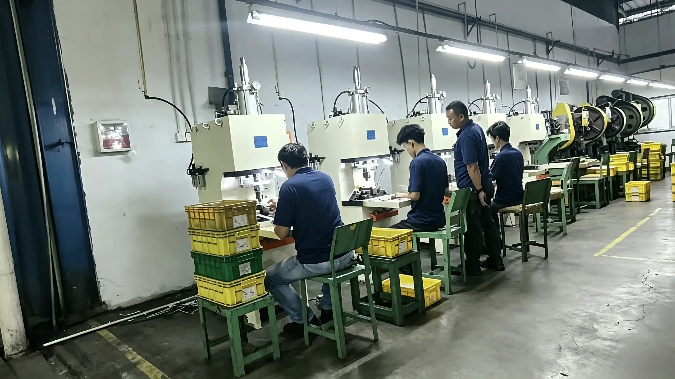
The workshop shown here is a useful example.
Several compact hydro-pneumatic presses are arranged as individual operator stations. Each machine has its own tooling area, and operators load and remove parts manually. The application information associated with the image identifies the operation as spoon embossing using a JRA-series hydro-pneumatic booster cylinder.
Behind these workstations are older, heavier presses with large exposed rotating components. From the visible flywheel-like structures and mechanical transmission layout, these machines appear more consistent with traditional mechanical or flywheel-type presses than with conventional hydraulic presses.
That distinction matters because the two technologies produce force in fundamentally different ways.
A traditional mechanical press typically follows a power path such as:
Electric motor → flywheel → clutch/crank mechanism → slide → tooling
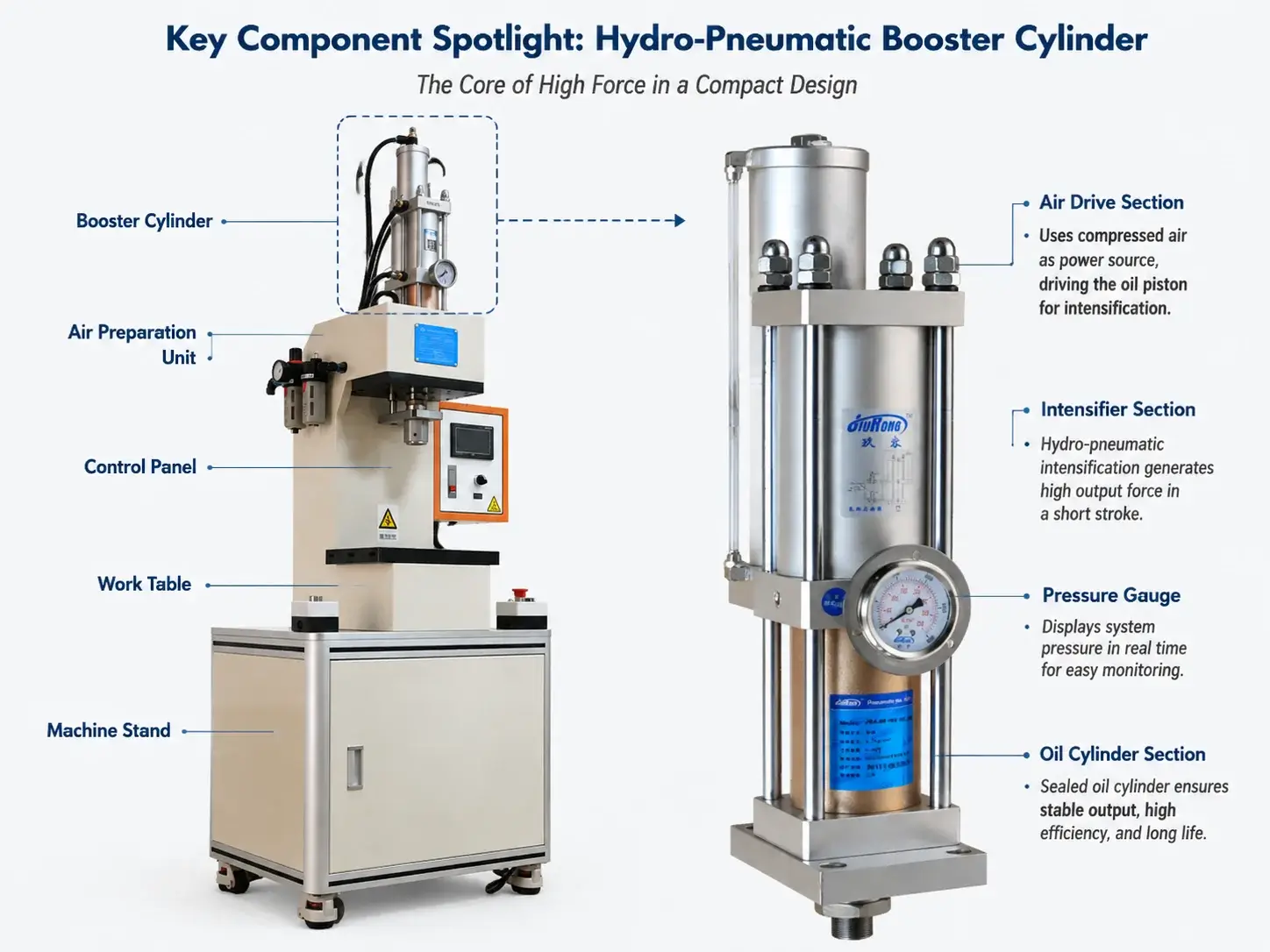
A hydro-pneumatic booster press instead uses compressed air as its primary power source and combines pneumatic movement with hydraulic intensification during the high-force portion of the cycle.
The JiuRong booster-press compressed air as the power source and identifies the hydro-pneumatic intensification principle as the mechanism used to combine relatively fast motion with higher output force. It also lists forming, punching, riveting, assembly, and cutting among supported machine applications.
This difference in architecture changes how the machine behaves on the production floor.
Mechanical Press: Store Energy, Then Release It Through the Stroke
A conventional flywheel mechanical press stores rotational energy in the flywheel. Through the clutch, crankshaft, connecting rod, and slide mechanism, that rotary motion becomes a fixed reciprocating stroke.
Its force capability is closely related to the crank position.
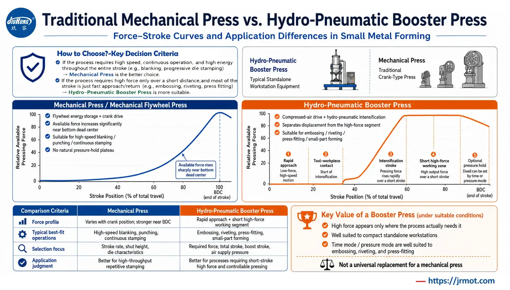
The press does not normally provide the same available force at every position in the stroke. Maximum usable forming capability is generally concentrated toward the lower portion of the stroke, near bottom dead center.
That operating principle works extremely well for processes such as:
- sheet-metal blanking;
- high-speed punching;
- progressive-die stamping;
- piercing;
- repetitive shallow forming;
- operations where a fixed stroke and high cycle rate are desirable.
For these applications, the mechanical press is not an outdated technology. It remains one of the most productive machine architectures available.
Its weakness appears when the production requirement changes.
Suppose the tool needs 150 mm of movement to clear the workpiece, but the actual high-force deformation takes place only during the final few millimeters.
A mechanical press still carries out the entire motion according to its crank geometry.
The machine cannot simply decide that the first part of the stroke is “travel” and the final portion is “power.” The kinematic relationship is built into the mechanism.
That is where the hydro-pneumatic approach becomes interesting.
Hydro-Pneumatic Booster Press: Separate Travel From High-Force Work
A hydro-pneumatic booster press is based on a different idea:
The machine does not need maximum force during the entire stroke.
Instead, the operating cycle can be divided into stages.
A simplified sequence is:
Rapid approach → tool/workpiece contact → pressure intensification → high-force working stroke → optional pressure hold → return
The attached machine manual confirms this staged control architecture. In automatic operation, the equipment can execute a pre-press movement, transition into the intensification stage, hold pressure when required, and then return. Both time-based and pressure-based operating modes are provided in the documented control sequence.
In pressure mode specifically, the machine advances through the pre-press stage, intensifies until the set working pressure is reached, performs the configured hold stage, and then returns.
That separation between travel stroke and high-force stroke is one of the most important engineering reasons to consider a booster press.
The machine can use pneumatic motion where high force is unnecessary, then activate hydro-pneumatic intensification only when the process actually requires it.
The Important Difference Is the Force Profile
It is tempting to compare presses only by tonnage:
“This machine is 10 tons. That machine is 10 tons. Therefore they are equivalent.”
They are not necessarily equivalent.
A press application should be evaluated using several questions:
- How much force is required?
- At what position is that force required?
- Over what distance must that force remain available?
- Is impact energy important, or is controlled pressing force more important?
- Does the process require pressure holding?
- What production frequency is required?
- How much tool clearance is necessary?
- How heavy is the moving tooling?
The attached JRI-A selection information reflects the same engineering logic. Its selection inputs include required high-pressure output, total stroke, boost stroke, air-supply pressure, worktable dimensions, closed height, operating frequency, and return-force requirement.
In other words:
Press tonnage alone is not enough to select a hydro-pneumatic booster press.
The relationship between total travel and the required high-force working stroke is particularly important.
Why the Booster Press Fits Many Small Metal-Forming Operations
Consider a spoon embossing operation like the one represented in the workshop image.
The operator places the workpiece into the fixture.
The upper tool needs to move down rapidly.
Until the tool reaches the workpiece, very little forming force is required.
Only after contact does the process need substantial pressing force to create the embossed geometry.
After a relatively short working stroke, the tool returns and the operator unloads the part.
The useful force profile therefore looks more like:
Longer low-load travel + short high-force forming stroke
rather than:
High force required throughout the entire motion
That is exactly the type of process structure in which hydro-pneumatic intensification makes engineering sense.
The general JiuRong press documentation identifies applications including thin-sheet punching, embossing, forming, riveting, bending, and shearing.
This does not mean that every embossing or riveting operation should use a booster press.
It means these processes often contain the motion pattern that makes the technology worth evaluating.
Mechanical Press vs. Hydro-Pneumatic Booster Press
| Engineering Consideration | Traditional Mechanical / Flywheel Press | Hydro-Pneumatic Booster Press |
|---|---|---|
| Primary energy source | Electric motor and rotating flywheel | Compressed air with hydraulic intensification |
| Force transmission | Crank / eccentric / connecting-rod mechanism | Pneumatic movement plus hydro-pneumatic intensification |
| Motion profile | Mechanically defined stroke | Staged approach, intensification, hold, and return |
| High-force region | Strongly related to crank position | Concentrated in the designed boost stroke |
| Stroke flexibility | Primarily determined mechanically | Process stages can be adjusted within machine design limits |
| Pressure holding | Not a natural strength of the crank mechanism | Can be incorporated into the operating cycle |
| High-speed stamping | Strong application | Not usually the primary reason to choose it |
| Progressive dies | Well suited when machine and die are matched | Generally not its main target application |
| Embossing | Suitable in many cases | Particularly relevant where the force stroke is short |
| Riveting / staking | Possible | Common candidate application |
| Press fitting | Possible but often not the natural choice | Common candidate application |
| Cutting / punching | Very strong for high-speed stamping | Supported for suitable force, stroke, and frequency ranges |
| Force adjustment | Usually involves tooling/machine setup and operating parameters | Output can be influenced through regulated air pressure within the machine’s designed range |
| Flywheel / crank drivetrain | Required | Not required |
| Conventional hydraulic power unit | Not required | Typically not required as an external power unit |
| Selection focus | Tonnage, energy, stroke, SPM, shut height, die characteristics | Force, total stroke, boost stroke, air pressure, workspace, opening/closed height, cycle frequency |
The table should not be interpreted as a ranking.
It describes two different machine philosophies.
Advantage 1: High Force Only Where the Process Needs It
This is probably the most important advantage of the hydro-pneumatic booster concept.
In many pressing operations, the majority of the motion is simply positioning.
The tool travels toward the workpiece.
No significant deformation takes place.
Once contact occurs, force rises sharply and the actual forming, riveting, cutting, pressing, or embossing operation occurs over a much shorter distance.
A booster press allows these two requirements to be treated separately.
That can make the machine particularly attractive when:
Total stroke >> required high-force stroke
This is why engineers selecting such a machine should distinguish clearly between total stroke and boost stroke.
Advantage 2: A Compact Alternative for Dedicated Workstations
Look again at the production line.
The booster presses are arranged as independent operator stations rather than as one large central press.
That arrangement can be useful when a factory needs separate machines for individual secondary operations such as:
- logo embossing;
- staking;
- riveting;
- small-component forming;
- press fitting;
- trimming or cutting;
- dedicated assembly operations.
Instead of making every task depend on a large general-purpose press, manufacturers can assign a compact machine to a specific operation.
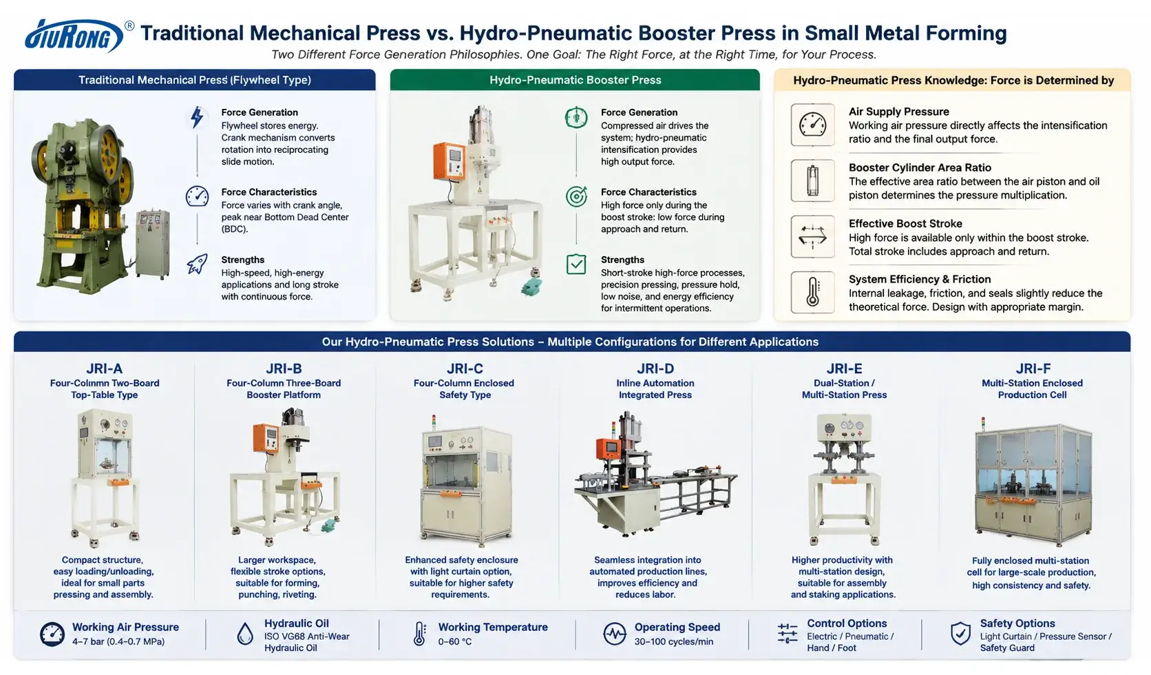
JiuRong also has JRI-B type, a four-column semi-open machine structure and lists optional safety light curtains and pressure sensors.
Whether this workstation approach is economically preferable depends on tooling, production volume, labor strategy, floor layout, and cycle requirements. It should therefore be treated as an application decision rather than a universal cost advantage.
Advantage 3: Pressure-Based Operation Can Be Useful for Process Control
Mechanical presses are fundamentally position- and mechanism-driven machines.
A hydro-pneumatic booster press can also be configured around pressure-related process logic.
According to the attached machine manual, the documented control system can operate in a pressure mode in which intensification continues until a set working pressure is reached, followed by a configurable holding stage. The system also provides monitoring of current, set, and previous pressure values.
For certain operations, that changes the way engineers think about the process.
Instead of asking only:
“Did the slide reach this mechanical position?”
they may also be able to ask:
“Did the pressing cycle reach the required pressure condition?”
That can be useful in pressing, riveting, assembly, and forming operations where force behavior matters.
It should not, however, be confused with a full closed-loop servo press force-displacement monitoring system unless the machine is specifically equipped and validated for that capability.
Pressure monitoring and full force-displacement process control are not automatically the same thing.
Advantage 4: No Large Flywheel or Conventional Hydraulic Power Unit
A mechanical press requires its mechanical drivetrain: flywheel, crankshaft or eccentric mechanism, connecting components, bearings, clutch/brake system, and the associated machine frame.
A conventional hydraulic press uses a different architecture centered around hydraulic power generation and control.
A hydro-pneumatic booster press follows neither of these architectures.
Its primary power source is compressed air, while hydraulic oil is used internally as part of the intensification mechanism. For example, the JRI-B source specifies compressed-air operation and ISO VG68 anti-wear hydraulic oil.
This can simplify the machine architecture for suitable applications.
But one important claim should be avoided:
Compressed air does not automatically mean “more energy efficient.”
Compressed air itself requires energy to generate.
A meaningful energy comparison must include the compressor, duty cycle, machine utilization, standby losses, required force, cycle frequency, and the specific competing machine.
Therefore, without measured plant data, it would be misleading to claim a fixed percentage of energy savings.
A more defensible engineering statement is:
A hydro-pneumatic booster press can avoid the need for a continuously operating conventional hydraulic power unit in applications where high force is required only during a short portion of the cycle.
That is a machine-architecture advantage, not a fabricated energy-saving percentage.
Advantage 5: The Pressing Cycle Can Be Adapted to the Process
The attached JiuRong manual documents manual and automatic operation, as well as time-based, pressure-based, single-step, and continuous operating functions.
This allows the machine cycle to be organized around stages such as:
Pre-press time → boost time / target pressure → hold time → return
For a simple embossing workstation, hold time might not be necessary.
For another forming or assembly process, a controlled dwell may be useful.
That flexibility is particularly relevant when one machine architecture is being adapted to several low- or medium-complexity secondary operations rather than a single fixed high-speed stamping process.
Where the Mechanical Press Is Still the Better Choice
A credible comparison needs to say this clearly:
A hydro-pneumatic booster press is not a universal replacement for a mechanical press.
If the production requirement involves:
- very high stroke rates;
- progressive dies;
- continuous coil-fed stamping;
- blanking where available flywheel energy is important;
- large production volumes optimized around dedicated stamping tooling;
- processes already well matched to a fixed mechanical stroke;
then the mechanical press may remain the better machine.
Replacing it with a booster press simply because the latter is compact or easier to control would make little engineering sense.
The best technology depends on the process.
Where a Booster Press Deserves Serious Consideration
A hydro-pneumatic booster press becomes particularly worth evaluating when several of the following conditions occur together:
- the machine needs relatively generous tool approach clearance;
- actual high-force deformation occurs only over a short distance;
- the process is embossing, riveting, staking, pressing, forming, assembly, or suitable punching/cutting;
- individual workstations are preferred;
- adjustable working force is useful;
- dwell or pressure-based operation is required;
- a conventional flywheel drivetrain is unnecessary for the required production rate;
- a large hydraulic power unit would add more system complexity than the application requires.
That is a much stronger engineering case for the technology than simply saying:
“A booster press is better than a mechanical press.”
It often is not.
But for the right force-versus-stroke profile, it can be a much better fit.
Do Not Select a Booster Press by Tonnage Alone
Before specifying a machine, collect the actual process data.
At minimum, the attached selection documentation indicates that engineers should consider required working force, workspace, opening height, booster-cylinder size, stroke, plant air pressure, operating frequency, and tooling-related return requirements.
In practical terms, the application review should answer:
- Required pressing force
What force does the process actually require? - Total stroke
How far must the tooling travel between fully open and working position? - Required high-force stroke
Over what distance is the forming force really needed? - Plant air pressure
What pressure is reliably available at the machine during production? - Cycle frequency
How many cycles per minute are actually required? - Tooling dimensions and opening height
Does the machine provide enough working envelope and loading clearance? - Moving tool weight and return requirement
Can the return system safely lift the tooling? - Pressure-hold requirement
Does the process need an actual dwell under load? - Automation level
Manual loading, semi-automatic operation, or integration into an automated cell? - Safety concept
Guarding, two-hand control, light curtains, emergency stop, tooling access, and risk assessment must match the final application.
The machine manual explicitly warns that safety devices should be checked before operation and that adjustment or maintenance should not be performed while the machine is running.
Safety is part of press selection, not an accessory added after the machine is purchased.
One More Selection Detail: Theoretical Force Is Not the Same as Application Force
Another important point appears in the JRI-B product documentation.
Its selection warning states that actual output should be considered at approximately 80% of theoretical output for selection purposes, while also accounting for the actual pressure available from the factory air source; the referenced theoretical output is based on 6 kg/cm² compressed air.
That means engineers should not simply read a theoretical tonnage value and design the application exactly at that number.
Real selection requires margin and verification against actual air-supply conditions.
This is another reason why:
“I need a 10-ton press” is not yet a complete specification.
Force requirement, available air pressure, boost stroke, cycle rate, tooling, and operating conditions still need to be checked.
The Practical Decision
If your production process is high-speed stamping, blanking, or progressive-die work, a traditional mechanical press may be exactly the machine you should keep using.
But if your process looks more like this:
Load part → rapid approach → contact → short high-force press → optional hold → return → unload
then it is worth asking whether a large flywheel-driven machine is really necessary.
For embossing, riveting, press fitting, assembly, small forming, and similar secondary operations, the hydro-pneumatic booster press offers a different way to design the workstation:
Use fast movement for travel. Use intensified force only for the part of the stroke that actually performs the work.
That is the real advantage.
Not “more advanced.”
Not “always faster.”
Not “always more energy efficient.”
And certainly not “a replacement for every mechanical press.”
It is simply a machine architecture that can match the physics of short-stroke, high-force manufacturing operations very well.
Choosing the Right Press for Your Application
Before replacing an existing mechanical press—or specifying a new booster press—compare the actual force profile of the process rather than the machine names.
Define:
Required Force + Total Stroke + High-Force Stroke + Tooling Envelope + Air Supply + Cycle Rate + Hold Requirement
From those parameters, an application engineer can determine whether a mechanical press, hydro-pneumatic booster press, hydraulic press, or another press technology is the more appropriate solution.
For a hydro-pneumatic application, the next step is not simply to request a tonnage.
It is to provide the real process conditions and let the press be selected around the operation.
 Two Pressing Points, One Setup? What a Dual-Head Riveting Station Must Get Right
  How to Choose a Cost-Effective Actuator for a Riveting Press
  Why a Booster Cylinder Fits the Punching Station of a Long Aluminum Profile Machine
  When Hydro-Pneumatic Booster Cylinders Fit Riveting, Clinching and Press-Fit Equipment
Leave a Reply