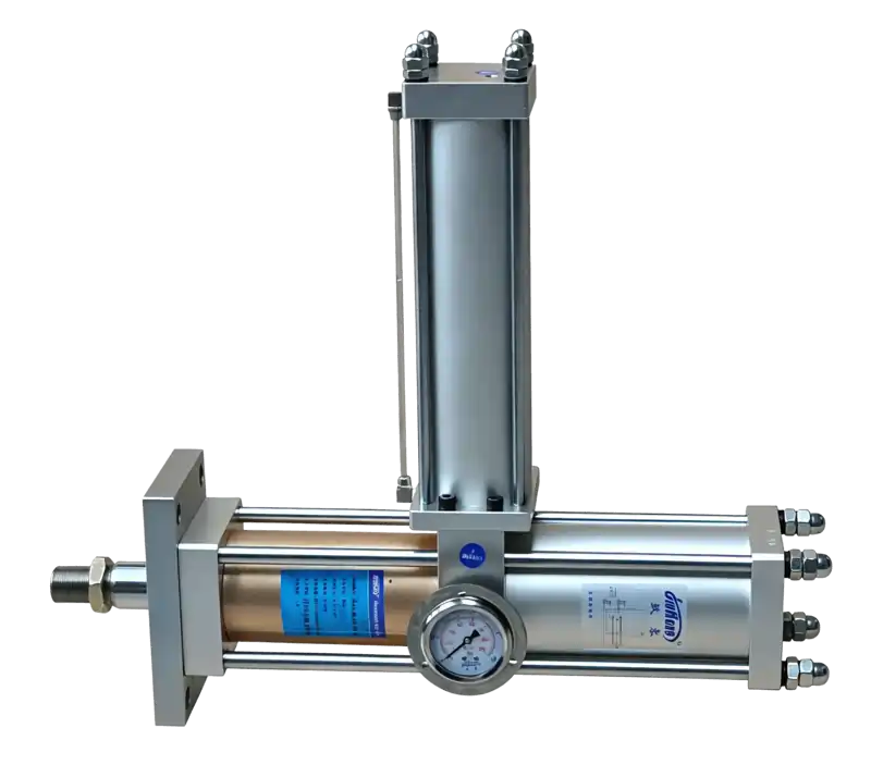
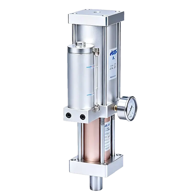
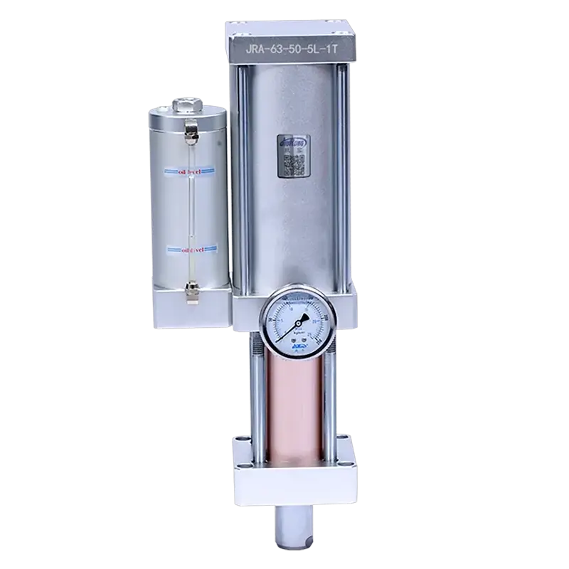
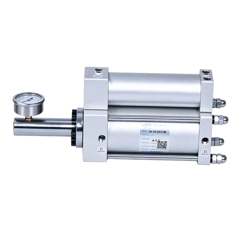
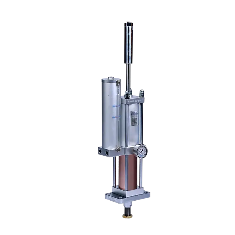
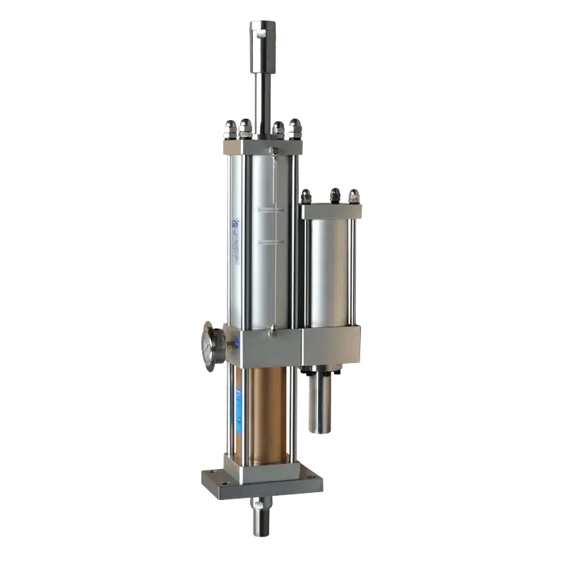
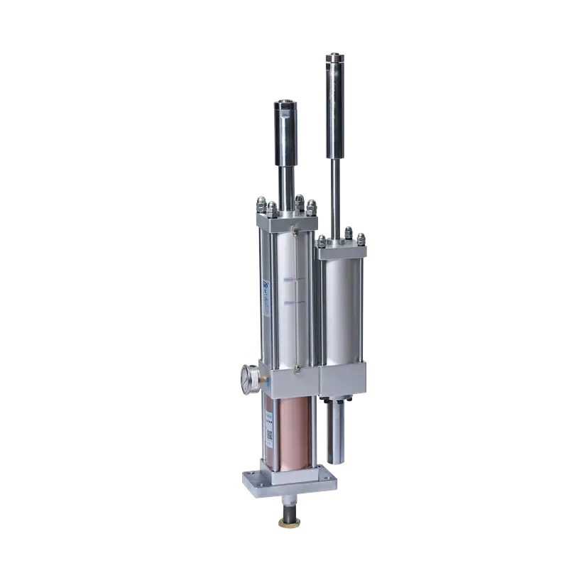
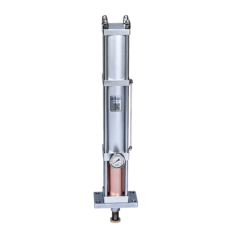
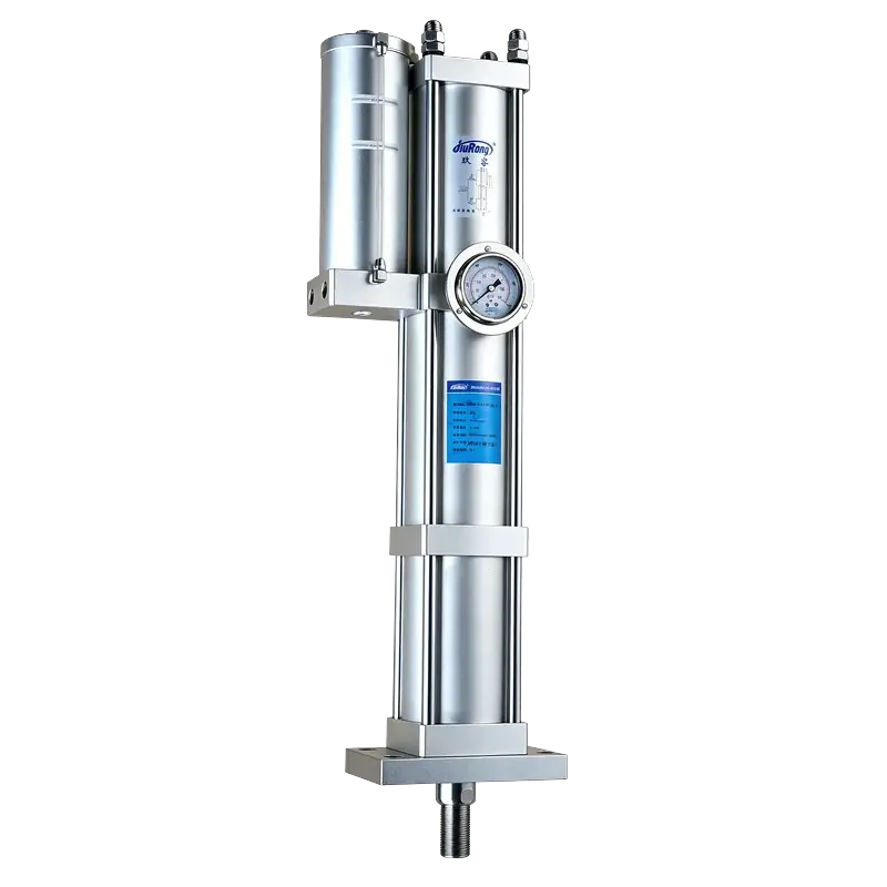
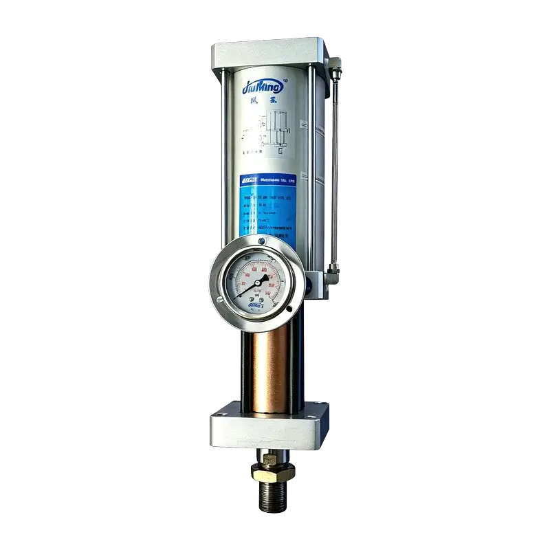
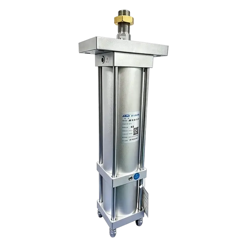
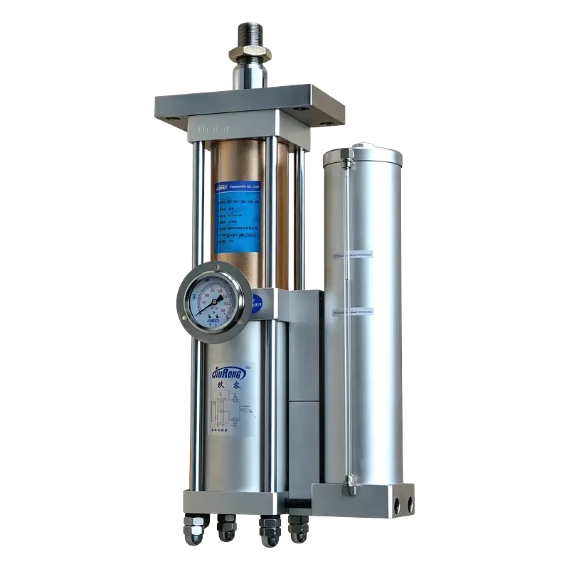
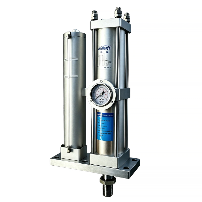
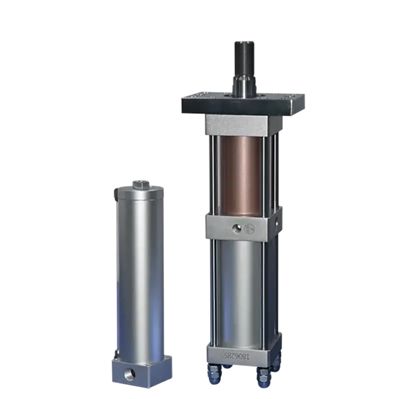
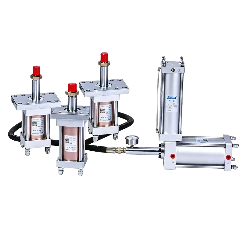
JiuRong® Hydro-pneumatic Boosting Cylinders Series

JiuRong® Hydro-pneumatic Boosting Cylinders Series

Energy‑saving hydraulic power from low‑pressure air

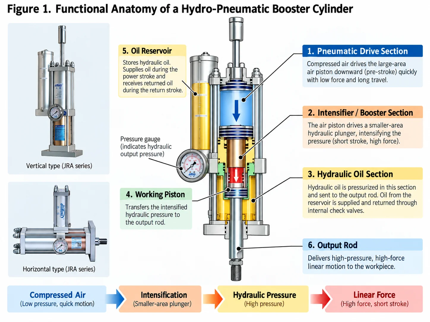
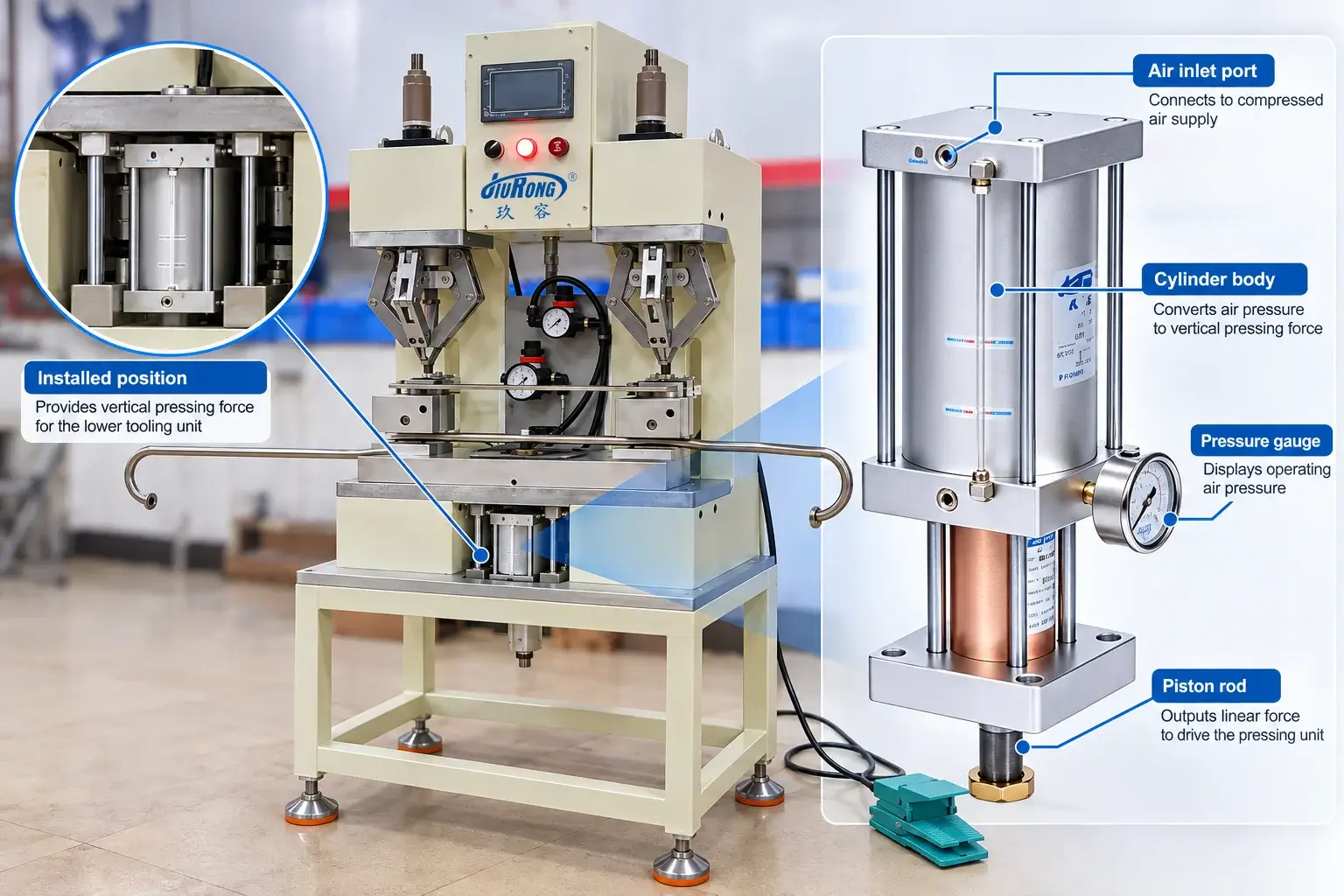
Principle: A hydro-pneumatic booster cylinder converts low‑pressure compressed air (0.2–1.0 MPa) into high‑pressure hydraulic oil (up to 50 MPa) via a differential piston area. It delivers controlled, high‑force linear motion for pressing, riveting, punching, and crimping operations – without external hydraulic pumps.

50:1Boost Ratio
≤ 0.02 mmRepeatability
1–150 TOutput Force
50–300 mmStroke

Quick qualification

Is a Hydro-Pneumatic Boosting Cylinder Right for Your Machine?

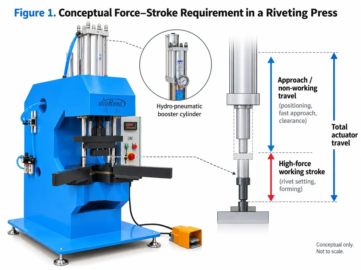
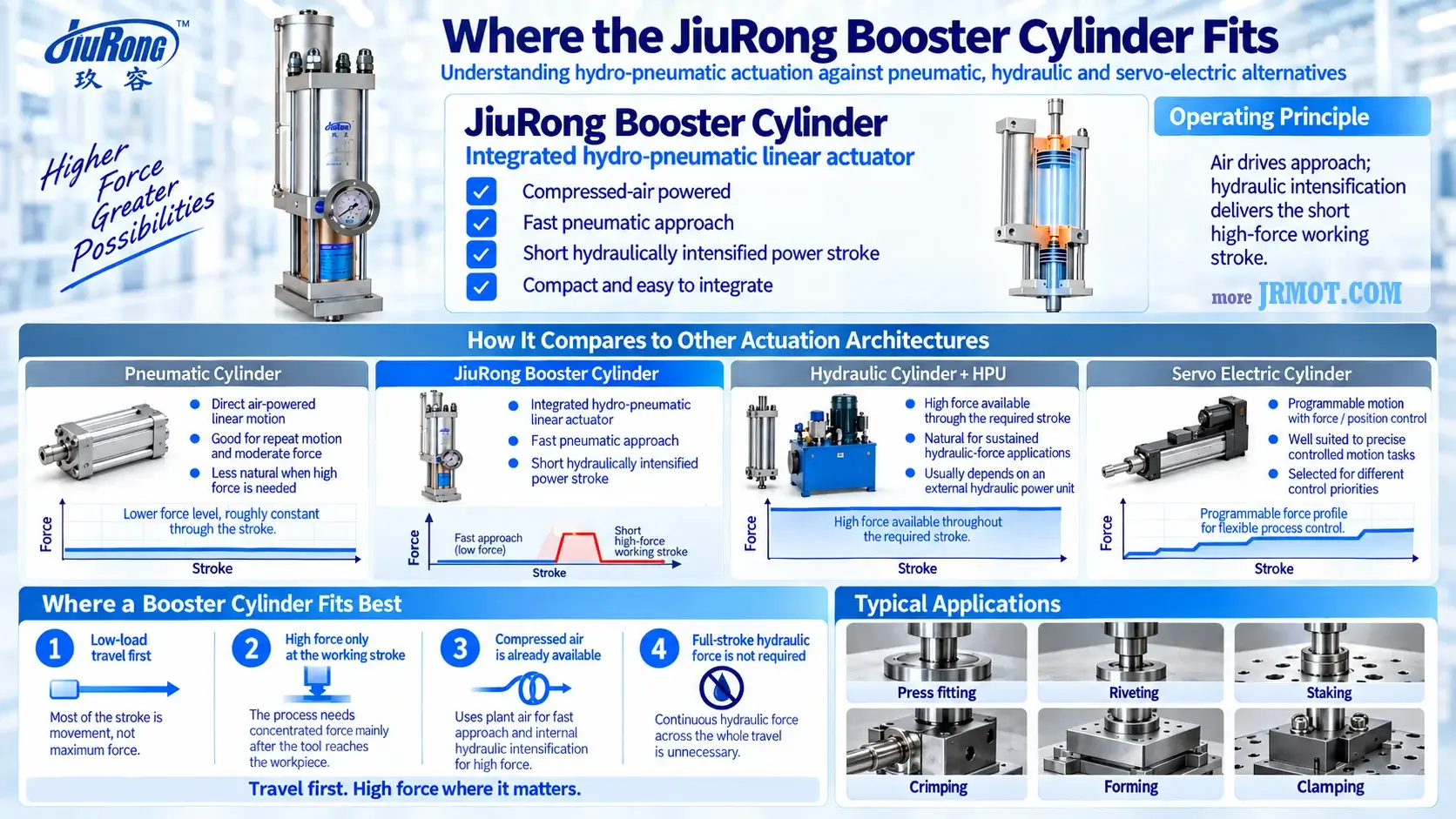
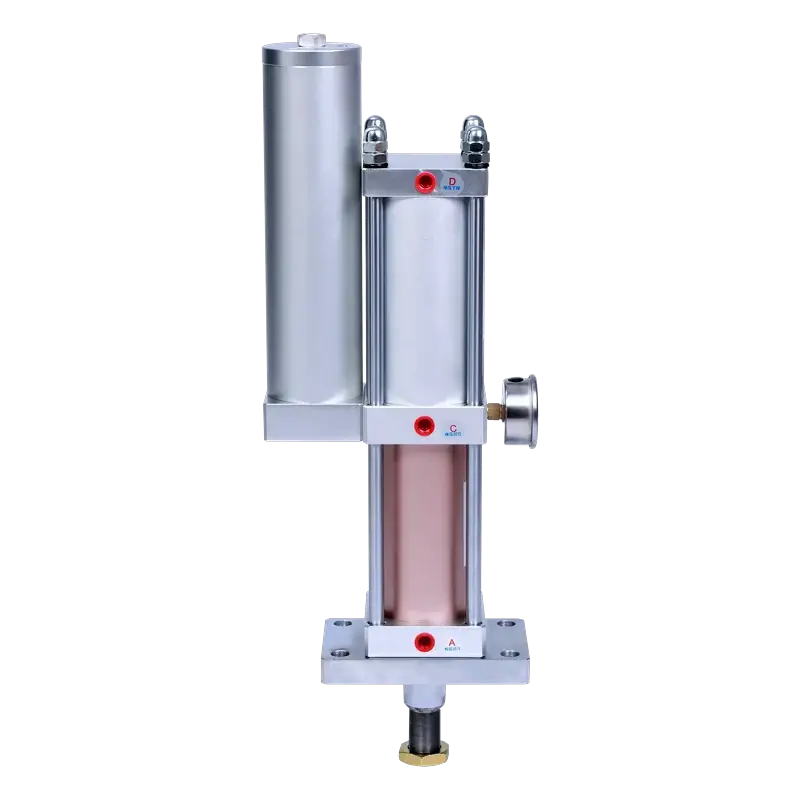
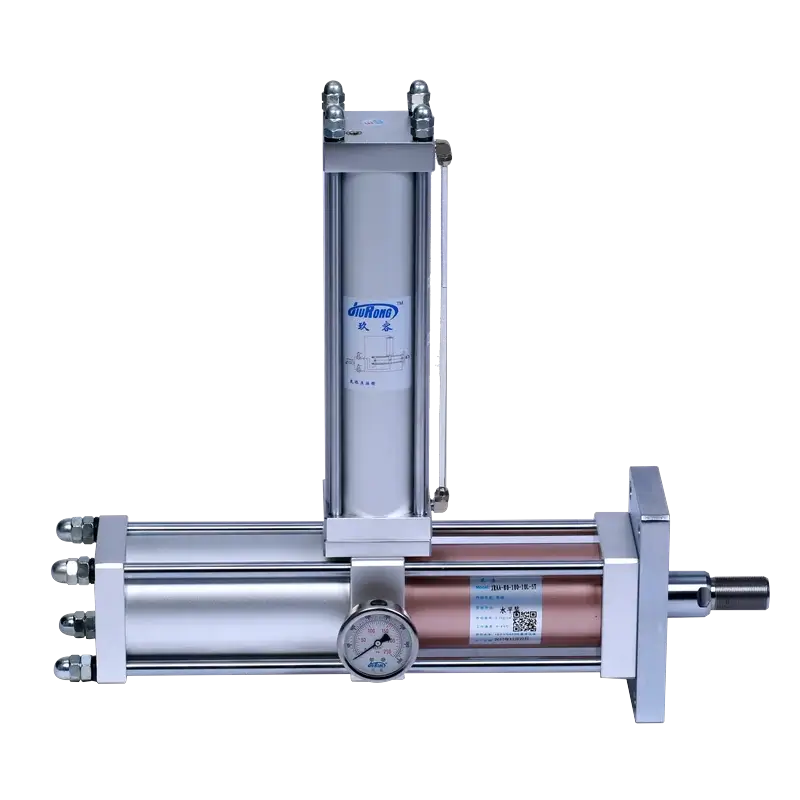
Start here when an ordinary pneumatic cylinder cannot provide enough force, but a complete hydraulic power unit would add unnecessary space, heat or maintenance. A hydro-pneumatic boosting cylinder is designed for a fast unloaded approach followed by a short, controlled high-force working stroke.

Choose hydro-pneumatic when...

  • A pneumatic cylinder cannot provide enough force.You need higher pressing force while retaining the factory compressed-air supply.
  • The tool has a long approach but a short loaded stroke.Fast pneumatic travel reaches the workpiece before hydraulic force takes over.
  • You do not want a separate hydraulic power unit.The machine needs a compact, self-contained high-force actuator.
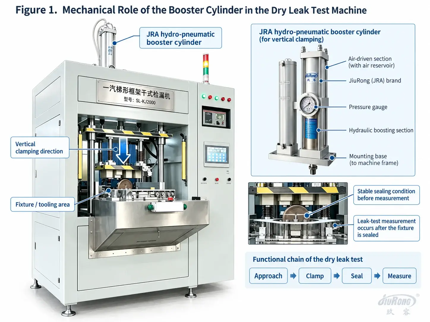
  • The process is press-fitting, riveting, punching or forming.The operation needs controlled force only near the end of travel.
  • The installation space or direction is restricted.Vertical, horizontal, reverse and separated layouts are available.
Check another option when...

  • High force continues through a long working stroke.Consider a hydraulic cylinder and power unit for sustained high-pressure duty.
  • Position, speed and force profiles must be programmable.Consider a servo-electric actuator for closed-loop motion and production data.
  • The motion is simple and requires only light force.A conventional pneumatic cylinder may be smaller and more economical.
Simple decision ruleFast unloaded approach + short high-force working stroke?

A hydro-pneumatic boosting cylinder is usually the right place to start.

See how it works

Working principle

How Air Becomes a Short High-Force Hydraulic Stroke

The standard pre-press cycle separates rapid travel from force generation, reducing energy use during idle approach.

Low Pressure Hydraulic Oil Compressed Air High Pressure Hydraulic Oil 1 2 3 4 P1 P4 P3 P2

Working Principle Description

  1. Reset Standby State
    Air supplied to P2 and P3, exhausted from P1 and P4. Both pre-press piston and boost piston remain at upper limit. The reservoir, cross passage and lower cylinder form a connected low-pressure circuit full of hydraulic oil.
  2. Pre-press Fast Forward Stroke
    Air supplied to P1 and P3, exhausted from P2. Compressed air acts on the oil surface in the reservoir. Hydraulic oil flows through the cross passage into the lower cylinder, driving the pre-press rod down rapidly to eliminate idle stroke and contact the workpiece.
  3. Boost Forming Stage
    Air supplied to P4, exhausted from P3. The boost piston drives the boost ram downward to seal the oil passage, enclosing the lower chamber. Oil pressure rises sharply to deliver high tonnage force and complete workpiece forming.
  4. Return Stroke Complete
    Air supplied to P3 and P2, exhausted from P4. Boost ram retracts and reopens the oil passage. Pressure releases and the circuit reconnects. Pre-press piston returns upward, oil flows back to the reservoir, finishing one full cycle.
Fast approachHigh-force strokeReturn
Engineering note: Output tables are theoretical values at stated inlet pressures. Size the cylinder from required working force and verified dynamic air supply, then apply the model-specific engineering margin. Approved drawings and quotations supersede summary web data.
Complete Model Range

18 hydro-pneumatic cylinder models across 5 cylinder types

Five cylinder types — standard pre-press, direct pressure, adjustable stroke, fast & compact, and special mounting. Choose a tab to focus on the models built for your machine; each card keeps its full specifications, features and applications.

Showing 18 models
Standard JRA Series
JRA Series

JRA — Standard Pre-press Type

The workhorse of the lineup. 4-step cycle: fast approach → slow pressing → boost forming → return. Vertical or horizontal mounting for general-purpose pressing, stamping, and riveting.

Force 1–40T Total Stroke 10–300mm Boost Stroke 5–50mm
  • 4-step cycle
  • Vertical & horizontal
  • Custom up to 150T
Applications: Stamping, riveting, pressing, crimping View JRA Series →
Standard JRAA Series
JRAA Series

JRAA — Horizontal Standard Type

Horizontal-mount variant of the JRA, designed for inline installation on automated lines and conveyor-fed systems where vertical space is limited.

Force 1–40T Mounting Horizontal Cycle 4-step
  • Horizontal inline
  • Automation-ready
  • Low profile
Applications: Automated lines, inline pressing, conveyor systems View JRAA Series →
Standard JRO Series
JRO Series

JRO — Compact Standard Type

Compact footprint standard pre-press cylinder for light-to-medium duty applications where space is constrained but full 4-step cycle performance is required.

Force 1–20T Stroke 10–150mm Cycle 4-step
  • Compact body
  • Light duty
  • Quick delivery
Applications: Light assembly, small parts pressing, benchtop tooling View JRO Series →
Direct JRE Series
JRE Series

JRE — Direct Pressure Type

Full-stroke high force with a 3-step cycle (no separate boost segment). Short stroke, high output, simple pneumatic-like operation — ideal for punching and marking.

Force 1–13T Stroke Short, constant Cycle 3-step
  • Full-stroke force
  • Simple control
  • Fast response
Applications: Punching, marking, short-stroke pressing, embossing View JRE Series →
Direct JREB Series
JREB Series

JREB — Direct Pressure Block Type

Block-mount direct pressure cylinder with integrated manifold. Compact rectangular body for close-pitch multi-cylinder arrangements on die sets.

Force 1–10T Mounting Block / manifold Pitch Close spacing
  • Manifold mount
  • Multi-cylinder arrays
  • Compact block
Applications: Multi-point punching, die sets, progressive tooling Request Engineering Data →
Direct JRU Series
JRU Series

JRU — Direct-acting Booster

A separate direct-acting booster for driving an external oil cylinder. It keeps the pressure-generation unit away from the working axis when machine layout requires separation.

Force 1–13T Layout Separate booster Ports 3-way
  • Remote pressure source
  • Simple 3-port
  • External cylinder drive
Applications: Remote cylinder drive, constrained machine layouts, custom axes View JRU Series →
Direct JRV Series
JRV Series

JRV — Direct-acting Flange Booster

A flange-mounted direct-pressure booster for vertically arranged external-cylinder systems and engineered multi-cylinder layouts.

Architecture Remote booster Mounting Flange vertical Selection Engineering review
  • Flange mounting
  • External cylinder drive
  • Multi-cylinder capable
Applications: Vertical press layouts, remote cylinders, engineered systems View JRV Series →
Adjustable JRB Series
JRB Series

JRB — Force-stroke Adjustable Type

Adjust the high-force power stroke length to match your application. Set the exact working window for different part heights without changing tooling.

Force 1–40T Adjust Power stroke Cycle 4-step
  • Power-stroke adjust
  • Variable part height
  • Precise setpoint
Applications: Variable-height parts, multi-tool stations, flexible production View JRB Series →
Adjustable JRC Series
JRC Series

JRC — Total-stroke Adjustable Type

Adjust the total approach stroke for varying die shut heights. The approach (low-force fast travel) length is adjustable while boost stroke remains fixed.

Force 1–40T Adjust Total stroke Shut Height Variable
  • Total-stroke adjust
  • Shut height control
  • Die changeover
Applications: Presses with varying die heights, tool changeover, R&D labs View JRC Series →
Adjustable JRD Series
JRD Series

JRD — Dual Adjustable Type

Both total stroke and power stroke are independently adjustable. Maximum flexibility for job shops and applications with frequently changing part geometry.

Force 1–40T Adjust Both strokes Flexibility Maximum
  • Dual adjustment
  • Independent setpoints
  • Job shop ready
Applications: Job shops, R&D, short-run production, frequent changeover View JRD Series →
Fast JRF Series
JRF Series

JRF — Fast Single-row Type

High-speed approach (250–500mm/s) for rapid cycling. Optimized flow paths reduce air consumption and cycle time for high-volume assembly and riveting.

Force 1–40T Speed 250–500mm/s Cycle Rate 25–45/min
  • High approach speed
  • Slim single-column body
  • 25–45 cpm
Applications: High-speed riveting, assembly, automated fastening View JRF Series →
Fast JRM Series
JRM Series

JRM — Fast Speed Type

The fastest in the range with cycle rates up to 60 per minute. Designed for high-volume automated production lines with die heads and small tooling.

Force 1–20T Speed Up to 500mm/s Cycle Rate 40–60/min
  • 60 cycles/min max
  • Automated line ready
  • Small die head
Applications: High-volume automated lines, die heads, electronics assembly View JRM Series →
Fast JRG Series
JRG Series

JRG — Compact Compound Type

Compound (two-stage) design in a compact body. High approach speed combined with adjustable boost force in a minimal footprint for tight installations.

Force 1–20T Design Compound 2-stage Footprint Compact
  • Compound design
  • Minimal footprint
  • High-frequency
Applications: Tight-space automation, high-frequency pressing, compact machinery View JRG Series →
Fast JRNT Series
JRNT Series

JRNT — Mini Reverse Compound Type

Ultra-compact reverse-mount compound cylinder for small automation cells and robotic end effectors. Minimal weight and size for high-speed indexing.

Force 1–8T Mounting Reverse mini Weight Ultra-light
  • Mini reverse
  • Ultra-lightweight
  • Robotic mounting
Applications: Robotic end effectors, small automation, indexing tables View JRNT Series →
Special JRT Series
JRT Series

JRT — Reverse Mounted Type

Rod extends upward (inverted mounting). Cylinder body mounts below the work surface for clean top-side access and overhead force delivery.

Force 1–40T Direction Upward (inverted) Mount Below table
  • Upward force
  • Below-table mount
  • Clean work surface
Applications: Upward pressing, table-mounted tooling, cavity forming View JRT Series →
Special JRP Series
JRP Series

JRP — Side-by-side Type

Two cylinders paired side-by-side for balanced force delivery across wider tooling. Up to 40% length reduction vs. a single large-bore cylinder.

Force 2×(1–20T) Config Dual parallel Length −40% vs single
  • Dual parallel cylinders
  • Balanced force
  • Space saving
Applications: Wide tooling, balanced pressing, long-span dies View JRP Series →
Special JRAB Series
JRAB Series

JRAB — Separate Reservoir Type

Oil reservoir is a separate unit connected by hydraulic hose. Allows the cylinder body to fit in tight spaces while the reservoir mounts remotely.

Force 1–40T Reservoir Remote Connection Hydraulic hose
  • Remote reservoir
  • Tight-space cylinder
  • Flexible mounting
Applications: Tight installations, confined machinery, retrofits View JRAB Series →
Special JRH Series
JRH Series

JRH — Air-oil Separated Type

Air cylinder and oil cylinder are completely separated, connected only by a hydraulic line. Eliminates any risk of air-oil mixing for cleanroom and food applications.

Force 1–30T Design Air-oil separated Cleanliness No mixing
  • Zero air-oil mix
  • Cleanroom compatible
  • Remote oil unit
Applications: Food packaging, cleanrooms, medical devices, electronics View JRH Series →

Choose & compare

Choose the Right Cylinder Type

Identify your main production constraint, then verify the recommendation against force, motion, mounting and application requirements.

Current recommendation

Standard Pre-press

A versatile cylinder for general pressing and assembly

JRA · JRAA · JRO
Why this fitsPress-fit, riveting, punching, forming
Main considerationBest general-purpose starting point

Verify the Recommendation

FamilyModelsForce rangeMotion profileMountingBest forKey trade-off
Standard Pre-pressJRA · JRAA · JRO1–40T standardFast approach + short power strokeVertical / horizontalPress-fit, riveting, punching, formingBest general-purpose starting point
Direct PressureJRE · JREB · JRU · JRVUp to 13T catalog rangeFull-stroke high pressureVertical / block / remoteMarking, crimping, bearing insertionSimpler motion, higher oil demand
Adjustable StrokeJRB · JRC · JRD1–40TAdjustable power and/or total strokeVerticalFlexible lines, short runs, R&DMore setup flexibility and components
Fast & CompactJRF · JRM · JRG · JRNTModel-dependent, up to 40THigh-speed approach + boostVertical / compact / reverseAutomated assembly and high-volume linesSpeed depends on stroke, air flow and load
Special MountingJRT · JRP · JRAB · JRHModel-dependentApplication-specific architectureReverse / parallel / remoteRetrofits, wide tooling, clean work areasRequires drawing-level installation review

Engineering selection

Size the Application Before Choosing the Model

Force, power stroke and available air must be checked together. Use this sequence for a defensible preliminary selection, then verify the result against the selected model's current data.

Selection sequence Process load → Design force → Pressure & bore → Oil volume & power stroke → Duty and installation checks

1 · Tell us about the application

Find your suitable Cylinder Type

Enter what you know. The recommendation updates immediately; no contact details are required.

2 · Preliminary recommendation

Based on current inputs

Standard Pre-press Type

Best starting point for a rapid approach followed by a short high-force stroke.

Minimum design force—
Stroke structure—
Candidate seriesJRA · JRAA · JRO
This result selects a product family and required design-force level—not a final model code. Bore, intensifier ratio, oil volume, return force and installation drawing still require model-data verification.
Engineering basisSee the formulas and verification logic behind this recommendation

Core sizing logic

Three calculations determine feasibility

Symbols and units are defined so the logic can be reviewed by buyers, designers and application engineers.

1

Establish design force

Apply an application factor to the force the process actually needs.

Fdesign = Fprocess × KF in kN. Preliminary K values: clamping 1.2; press-fit/riveting 1.3; forming 1.4; blanking 1.5; punching/marking 1.6. Confirm K from the actual process risk and acceptance criteria.
2

Verify pressure and usable force

Use effective piston areas and the pressure measured at the machine while cycling.

i = Aa ÷ Ap = (Da ÷ Dp)²Ph = Pin,dyn × i × ηpFavailable = Ph × Ah × ηmSelection condition: Favailable ≥ Fdesign. With MPa and mm², divide by 1,000 for kN.
3

Verify oil volume and power stroke

The intensifier must displace enough usable oil for the loaded travel.

Vrequired,mL = Ah,mm² × Spower,mm ÷ (1,000 × ηv)Seffective,mm = Vnominal,mL × 1,000 × ηv ÷ Ah,mm²Stotal = Spre + SpowerSelection condition: Vnominal ≥ Vrequired, equivalently Seffective ≥ Spower.
Dynamic pressureUse pressure at the cylinder inlet during the cycle—not the unloaded compressor setting.
Efficiency factorsηp, ηm and ηv must come from verified model data or be declared as preliminary assumptions.
Do not double-count lossesηv corrects usable oil volume and stroke; it is not multiplied into the static force equation again.
Secondary engineering checksAir demand, return force and long-stroke stability

Air consumption after model selection

Using air-piston area Aa, pre-stroke Spre, power stroke Spower and ratio i:

Vcycle ≈ [AaSpre + AaSpower/i + Aa(Spre + Spower)] × Pabs/PatmFree-air estimate only. Confirm valve Cv, tube size, pressure recovery and cycles/min with the selected model and circuit.

Return-force verification

The available retract force at dynamic pressure must exceed tooling weight, seal/friction resistance, springs and stripping load with an agreed margin.

Freturn,available ≥ Ftooling + Ffriction + Fstrip

Compression-rod stability

Long, compression-loaded rods require a buckling check using the actual rod, unsupported length and end condition.

Fcr = π²EI ÷ (KL)²Euler is an ideal-column screen, not final approval; eccentricity, guides, initial deflection and the required buckling safety factor must also be reviewed.

Calculation scope: These equations support preliminary engineering selection. Current model tables, approved drawings, measured operating conditions and JiuRong's written project confirmation govern procurement and installation.

Application evidence

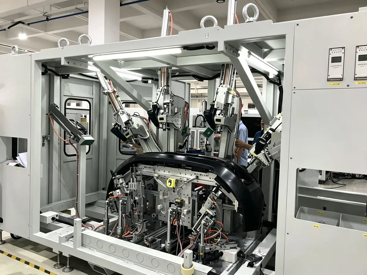
Where Hydro-Pneumatic Force Solves Production Problems

Typical process-to-series matches. Final selection depends on the actual tool, material and cycle.

JRA hydro-pneumatic cylinder punching an automotive radar sensor housing
Automotive electronics

Radar Sensor Housing Punching

JRA standard pre-press

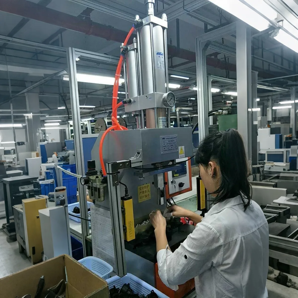
The cylinder rapidly approaches the radar sensor housing, then switches to a short high-force stroke for controlled hole punching. JRA reduces non-working travel time while keeping the final punching action stable.

JRA hydro-pneumatic cylinder press-fitting an electronic component into a housing
Electronics

Electronic Component Press-Fitting

JRA standard pre-press

JRA provides fast approach followed by a controlled power stroke to press electronic components into housings or fixtures. The two-stage motion supports repeatable insertion without a continuously running hydraulic power unit.

Hydro-pneumatic cylinder cutting copper electrical terminals in an automated station
Electrical components

Copper Terminal Cutting

JRA / fast series

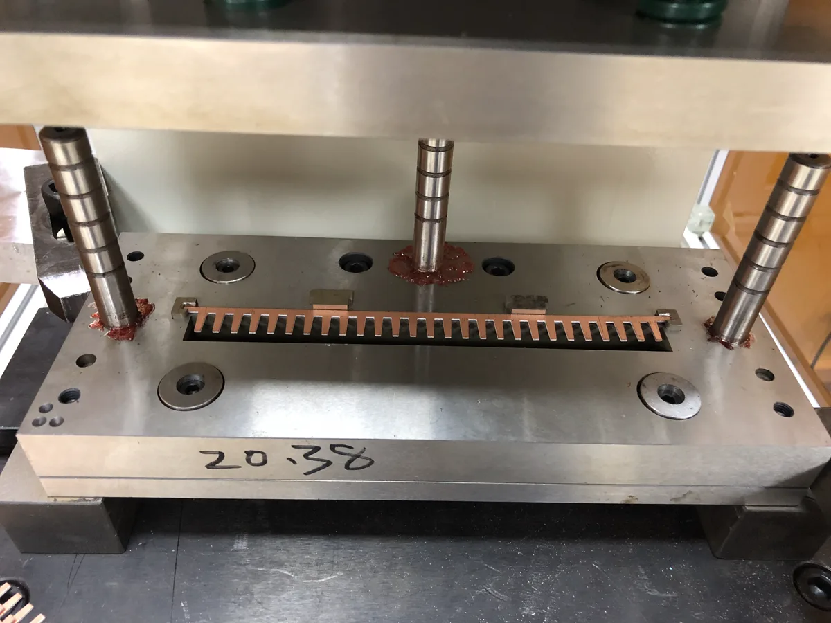
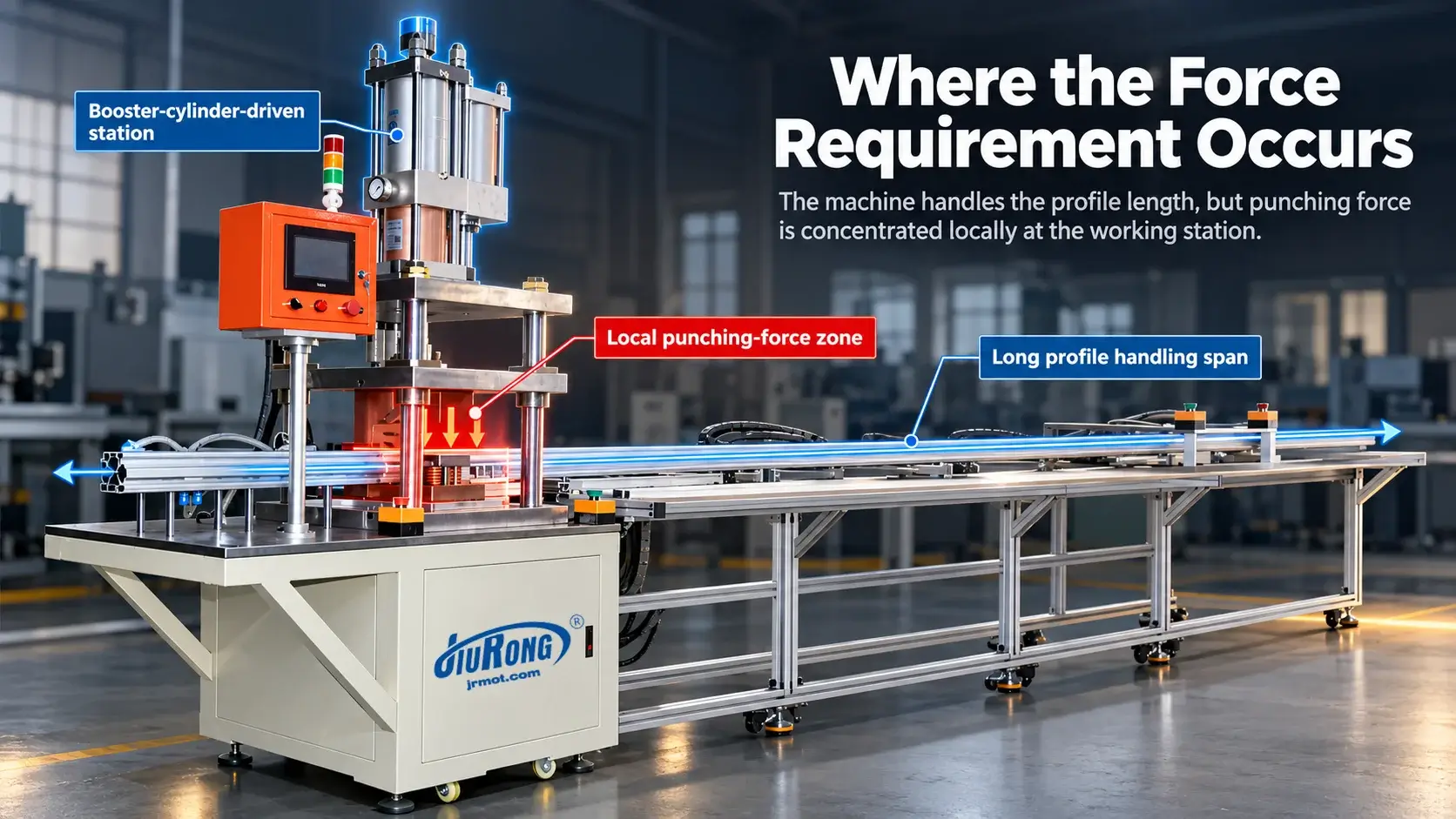
Copper terminal cutting requires concentrated force at the end of a short tool stroke. A standard or fast cylinder shortens approach time and supplies the localized cutting force needed in compact automated terminal-processing equipment.

Heavy JRA hydro-pneumatic cylinder punching an aluminum profile
Building materials

Aluminum Profile Punching

JRA heavy configuration

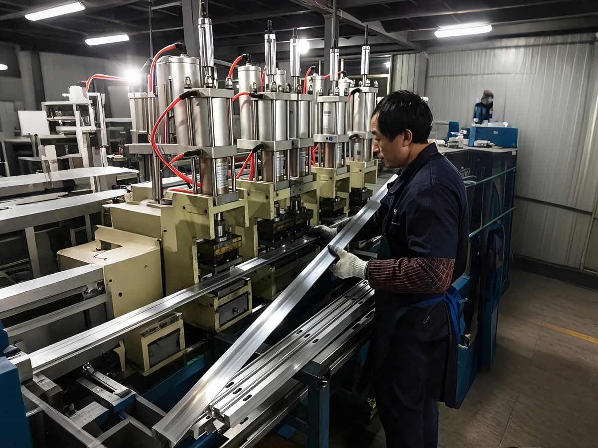
The cylinder advances quickly across the tooling clearance and generates high force only while punching the aluminum profile. A heavy JRA configuration suits intermittent stations that need strong output without a separate hydraulic power pack.

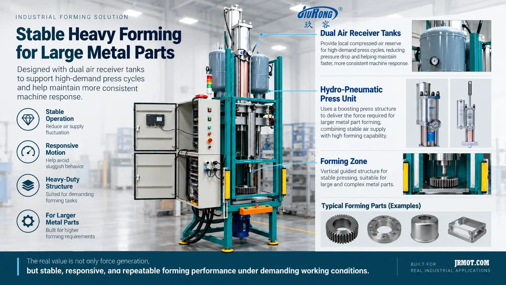
Engineered high-force hydro-pneumatic cylinder used for heavy-duty metal stamping
Hardware

Heavy-Duty Metal Stamping

Engineered high-force system

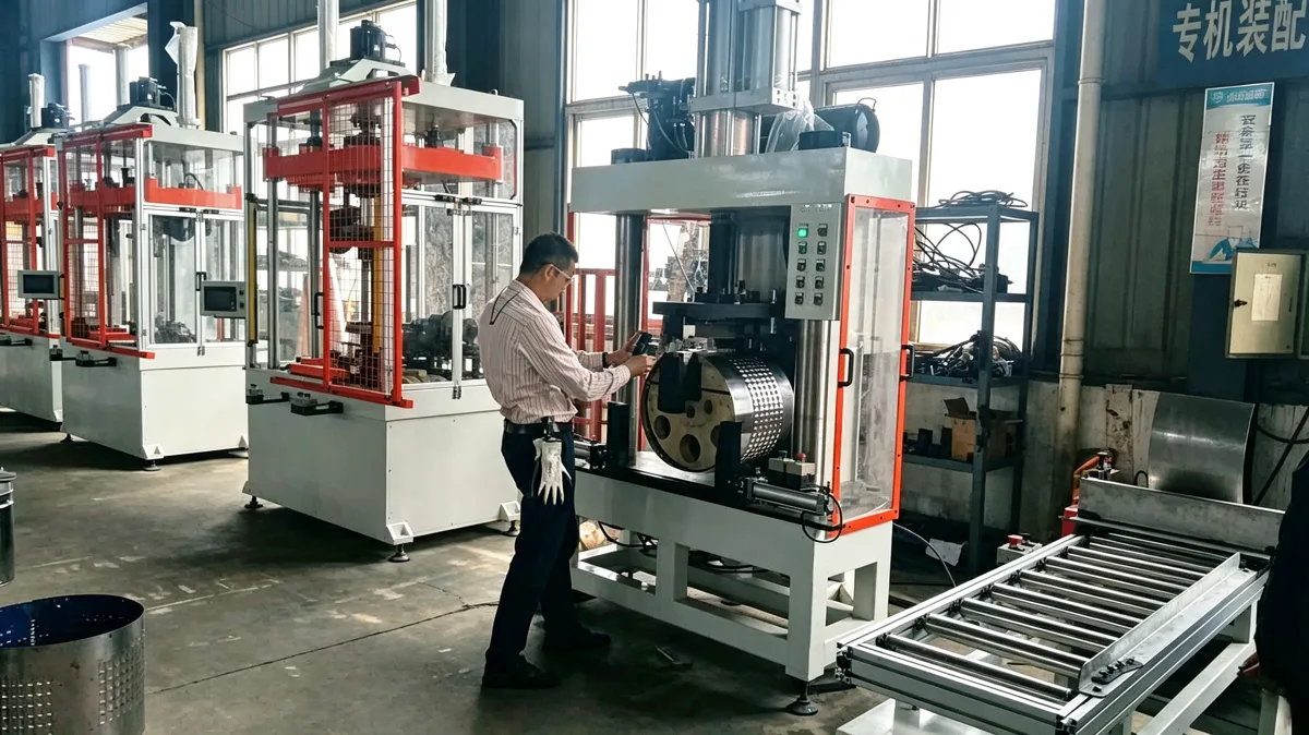
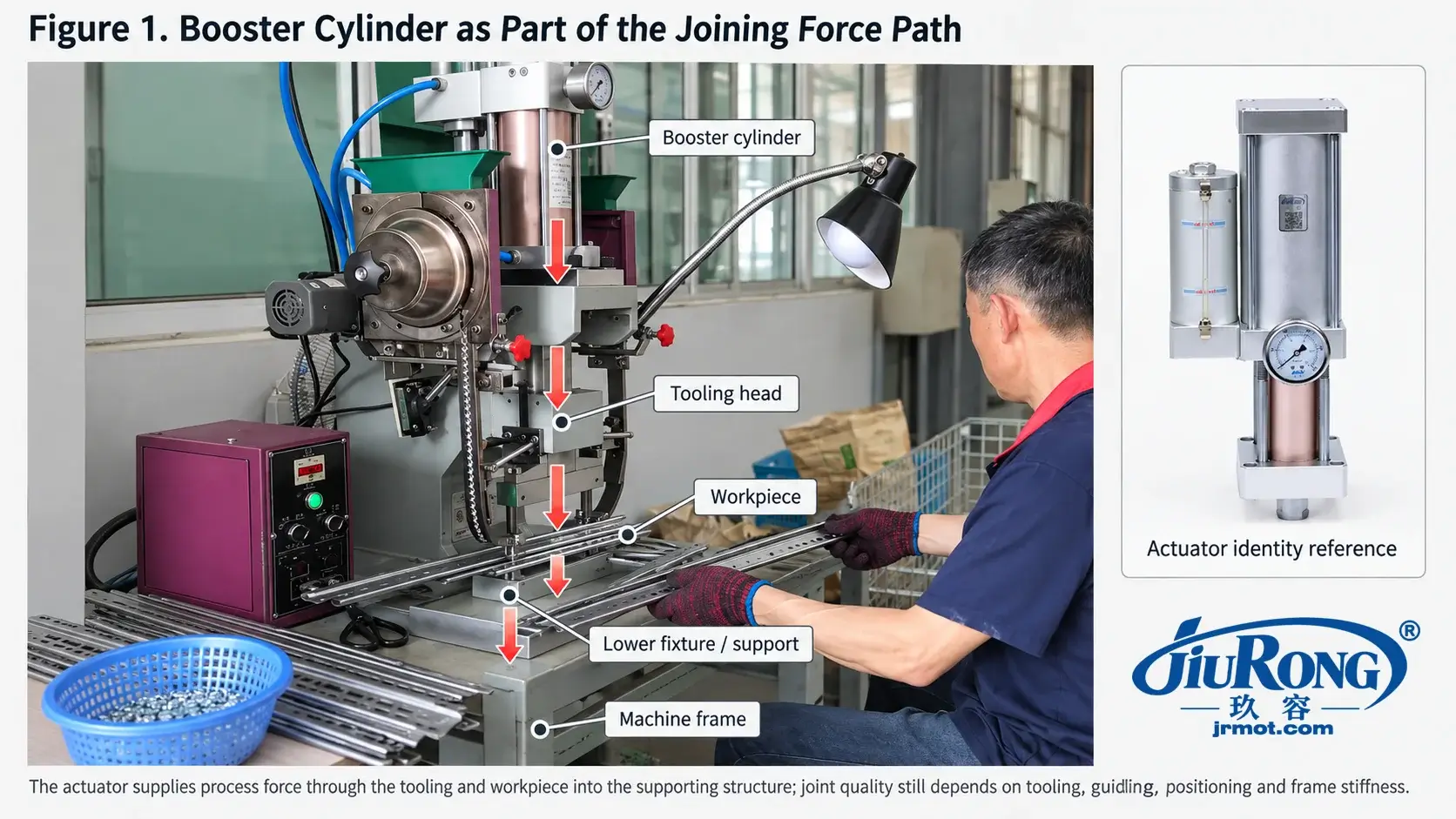
Heavy metal stamping requires the cylinder, machine frame and tooling to withstand the same forming load. This application uses a drawing-led configuration selected from material thickness, tooling geometry, working force and structural limits.

JRM high-speed hydro-pneumatic cylinder operating an automated die head
High-volume manufacturing

High-Speed Die-Head Operation

JRM high-speed

JRM reduces approach and return time in repetitive die-head operations to support shorter automated cycles. Final sizing must verify dynamic air flow, power stroke, moving tooling mass and sustained cycles per minute.

Application images illustrate representative installations. Published production results should only be stated where the corresponding project record and operating conditions are available.
Direct answers

Hydro-Pneumatic Cylinder FAQ

Practical answers for initial engineering evaluation.

How does a hydro-pneumatic boosting cylinder work?

Compressed air first produces a fast, low-force approach. Near the workpiece, a differential-area intensifier raises hydraulic pressure for a short high-force power stroke. The unit then decompresses and returns.

When should I choose pre-press instead of direct pressure?

Choose pre-press for long rapid travel followed by a short high-force operation. Choose direct pressure when high force is required through the complete, usually short, working stroke.

Is the nominal tonnage the usable production force?

Not automatically. Catalog output is normally a theoretical value at a stated air pressure. Tooling friction, pressure loss, cycle rate, duty factor and a suitable engineering safety margin must be included in final sizing.

What information is required for model selection?

Provide required working force, total stroke, high-pressure stroke, available air pressure, cycle rate, return force, mounting direction, available envelope and a tooling or installation drawing.

Can a booster cylinder replace a hydraulic power unit?

It can for many intermittent, short-power-stroke pressing operations. A hydraulic power unit is usually more suitable for continuous high-pressure duty, long high-force travel or multiple continuously controlled axes.

When is an electric cylinder a better choice?

Consider a servo electric cylinder when programmable position profiles, closed-loop position control, data feedback or frequent recipe changes are more important than compact pneumatic-to-hydraulic force multiplication.

Application engineering

Get the Right Model Before You Request a Price

Send the process data and installation drawing. We will recommend the cylinder family, model structure and next engineering checks.

Selection basis documentedDrawing-level confirmationCustom configurations available

Include these details

  • Working force and material/process
  • Total stroke and high-pressure stroke
  • Air pressure, cycle rate and dwell
  • Return force and installation direction
  • Available envelope or machine drawing
Request Model Recommendation →
Browse mode

Interested in learning more about JiuRong

Discover how our innovative solutions and advanced technologies can empower your projects to achieve more.

Get In Touch Now